
User manual


36
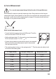
f) Continuity Test
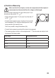
Make sure that all circuit parts, circuits and components and other objects of
measurement are disconnected from the voltage and discharged.
• Connect the black measuring line to the COM socket “8” and
DC
AC
DC
AC
V
the red one to the socket V, Ω, , “7”.
• Set the adjustment wheel “4” to the area , and the slider
“5” to “DC, , Ω“
• Connect the two measuring prods with the object to be
measured
• A resistance value up to 40 Ohm will cause a signal to sound
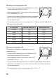
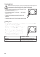
g) Battery Test
• In order to test the capacity of a battery, connect the black measurement line to the COM
plug “8“ and the red line to the plug “V, Ω.”
• Set adjustment wheel “4” according to the battery type, to
DC
AC
DC
AC
V
1.5 v. or 9 v., and switch “5” to “DC”.
• Place the red measuring tip on the plus pole and the
black measuring tip on the minus pole of the battery.
• The currently measured capacity can be read on the
scale display under the following values
BAT The battery is defective
REPLACE The battery should be exchanged soon
GODD The battery has adequate reserves