MultiSystem 4010 Operating Instructions MultiSystem 4010 Universal Portable Measuring System Operating Instructions Revision 1.5 / August 16, 2012 TKZ L3160-00-75.00EN / L3160-00-75.10EN © Hydrotechnik GmbH • All rights reserved Rev. 1.
MultiSystem 4010 Operating Instructions Contents 1. Safety ...................................................................................... 3 1.1. General Safety and Warning Hints .......................................... 3 1.2. Hints for the Use of the Measuring Instrument ........................ 3 1.3. Hints for the Use of Sensors and Cables................................. 3 1.4. Hints for the Use of rechargeable Batteries............................. 3 2. Introduction ..........................
MultiSystem 4010 Operating Instructions 1. Safety 1.1. General Safety and Warning Hints • • • • 1.2. Hints for the Use of the Measuring Instrument • • • • • • 1.3. Never expose the instrument to excessive heat or moisture; obtain the technical data. Do not store the instrument in humid or dusty locations or at temperatures below freezing point. Never dip the instrument into water or other liquids. Never let liquids come into the instrument.
MultiSystem 4010 Operating Instructions 2. Introduction Important Information The information contained in this section is important. If you neglect them, you might loose possible guarantee demands. 2.1. Range of Validity The manual on hand is valid for measuring instruments named "MultiSystem 4010". It adresses to the operator of this instrument, that means the person, who works with the instrument. The manual is not a technical manual.
MultiSystem 4010 Operating Instructions construction corresponds to the current norms and regulations. The manufacturer is doing product and market research for the further development and permanent improvement of their products. In case of faults and/or technical trouble please contact the Hydrotechnik service staff. We assure that suitable measures will be taken immediately. The Hydrotechnik GmbH guarantee regulations are valid, which we will send to you on demand. 2.4.
MultiSystem 4010 Operating Instructions Operator of the instrument Persons are authorized if they are trained in the operation of the instrument and have read and understood this manual completely. Personell for installation and maintenance Persons are authorized if they are trained in all aspects of the instrument and have read and understood this manual completely. 3. Description of the Measuring System 3.1.
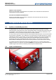
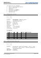
MultiSystem 4010 Operating Instructions 1/2/3 4 5 6 7 8 9 3.2.1. Input ch1 / ch2 / ch3 – analog inputs Input ch4 – combined input analog / frequency Input ch5 – frequency input USB interface Combined jack CAN / HYDROboot Power supply – power pack Digital input / output Analog inputs (ch1 / ch2 / ch3) Signal input Resolution Measuring rate Filter function Connector Protection type Error limits Linearity error Temp.coefficient 20mA (selectable 0 … 20 mA or 4 … 20 mA) 10 V (selectable 0 ... 10 V or 2 ...
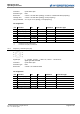
MultiSystem 4010 Operating Instructions Connector Protection type Error limits Linearity error Temp.coefficient 6 pole device jack IP40 ≤ ±0.15 % of final value (analog) / ≤ ±0.05 % of measured value (frequency) ≤ ±0.10 % of final value (analog) / none (frequency) ≤ 0.1 % per 10 °C (analog) / none (frequency) Pin assignment Pin 1 1 2 3 4 5 6 Ub*: 1: 2: 3.2.3. Function Signal I [mA] Frequency signal GND Ub* Direction signal Shield ISDS Ri. 50 Ω 4.75 kΩ Ci. 100 nF 1 nF Limitation 5.
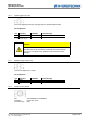
MultiSystem 4010 Operating Instructions 3.2.4. Digital trigger input (ch6) Pins of the digital input/output; the trigger input is separated galvanically. Pin assignment Pin 3 4 Function Signal* GND Limitation 33 V DC Protection type VDR transile diode *: 1 mA constant current Attention Damage to the instrument possible! This input may not be connected to inductive consuments directly (e.g. coil of a magnetic valve). Otherwise the instrument can be damaged. 3.2.5.
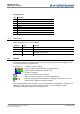
MultiSystem 4010 Operating Instructions Pin assignment Pin 1 2 3 4 5 6 7 8 Function GND power supply for MultiXtend or CAN sensors* DTR CAN_H TXD RTS from PC (input) GND RXD *: ~ 21.5 VDC / 200 mA (mains operation) / ~ Ub / 200 mA (battery) 3.2.7. USB interface Micro USB interface for PC communikation 3.3. Function Signal D+ Signal D– VCC Color green white red GND black Remarks twisted cable twisted cable delivers max.
MultiSystem 4010 Operating Instructions 3.4. Keyboard The MultiSystem 4010 is equipped with a valuable keypad that is insensitive against humidity and dirt. The 26 keys are occupied as follows: ...
MultiSystem 4010 Operating Instructions 3.5. Evaluation Software Important Instrument not compatible with elder software versions! Use HYDROcom 6 with at least version 6.3.0.20 for the communication with the MultiSystem 4010. Otherwise the measuring data cannot be transferred correctly. The current version is contained on the data CD of your instrument or in the dowload section of www.hydrotechnik.com. The evaluation software HYDROcom is part of the delivery.
MultiSystem 4010 Operating Instructions 4. Start-up 4.1. Check Delivery The measuring instrument is delivered by Hydrotechnik and transported by suited shipping companies. At the time of delivery you should check: • Does the number of delivered items corresponds with the Hydrotechnik delivery note? • Is the packing free of visible damage? • Are measuring instrument and accessories free of visible damage? • Are there any indications of rough treatment during transportation (e.g.
MultiSystem 4010 Operating Instructions Hints for the treatment of the batteries The life cycle of NiMH cells can be very long, but it depends on the conditions of use. Avoid a complete discharge, continuous charging and immediate re-charging after every use. This triggers the memory effect with a minimization of the battery capacity and possible remanent damage. You can regenerate the battery by several discharge and charge cycles. In case of low battery power a hint "Load batteries" will be displayed.
MultiSystem 4010 Operating Instructions Switch on: (> 2 sec.) Wait for the self-test until the measured values are displayed Use the instrument Switch off: (> 2 sec.) Information When using ISDS sensors the sensor parameters will be set automatically. When using other sensors you will have to program the parameters before you can execute measurements. 5.2. Select Operation Language Open function: [Device] Do selection: Confirm selection: Accept changes: 5.3.
MultiSystem 4010 Operating Instructions 5.4. Connect Sensors 1. Switch the instrument off. 2. Connect the desired sensors to the inputs (see section 3.2 on page 6). 3. Switch the instrument on. 5.5. Enter Sensor Parameters Information The sensor parameters will be detected automatically when you have connected ISDS sensors. You may skip this section. Information The parameters of sensors without ISDS functionality must be entered manually.
MultiSystem 4010 Operating Instructions Signal type Measuring range select the sensor output signal ("0/20 mA", "4/20 mA", "0/10 V", "2/10 V") enter beginning and end of the measuring range and confirm both entries with press to execute the automatic zero point equalisation; assure that the sensor has no load and press to run the equalisation; a possible zero point deviation will be calculated in the software you may enter a calibration table for the connected sensor after setting „Yes“ at the menu item „
MultiSystem 4010 Operating Instructions 5.7. Connect PC and transfer Measuring Data Information The software HYDROcom must be installed on your PC before you are able to transfer measuring data. 1. Switch on measuring instrument and PC. 2. Plug the delivered USB cable into the connector at the side of the instrument (see section 3.2 on page 6). 3. Plug the USB cable into an USB interface of your PC. 4. Wait until the instrument has been detected properly. 5.
MultiSystem 4010 Operating Instructions 5.9. Reset Instrument Important Information All customer-specific parameters and settings (channels, display, memory, presentation, …) and saved measuring data are deleted by a reset. Switch instrument off: Switch instrument on: Wait until the beginning of the initialization is displayed and then press: Select the desired language Confirm the reset: A red message will be displayed where the reset into the selected language is confirmed. 6.
MultiSystem 4010 Operating Instructions Numerical Input to enter the decimal point and confirm the input Use the numeric keys of the instrument. Press . The value „125.2“ is entered in this way: with Alphanumeric Input During the input in options requiring alphanumeric characters, the second occupations of the numeric keys is active.
MultiSystem 4010 Operating Instructions The current measured values are displayed after initialisation. You may select the shown channels in the display menu. Use one of two display modes: • • measured values with units (left image) measured values with minimal and maximal values (right image) The active display mode is displayed in the lower left corner. Press and to stop the refresh of the values (“freeze” the display). Press to toggle the display mode again to enable the refresh.
MultiSystem 4010 Operating Instructions 6.4. Configure Channels Highlight „Channels“ in the main menu and press : You can see a list of all twelve channels of the instrument. The first five are the physical input channels (see section 3.2 on page 6), C6 and C7 are the trigger input resp. output. The other channels can be used for calculations or may be occupied with digital input signals (e.g. CAN, option). Use the arrow keys to highlight a channels and press 6.4.1. to open it.
MultiSystem 4010 Operating Instructions How to use a Linearisation Table A linearisation table contains must- and is-values for several reference points of the sensor measuring range. They are determined during the calibration of the sensor and are used to (partly) compensate the linearisation error of the sensor. The measuring error of a sensor can be reduced significantly by using a linearisation table. The instrument can use linearisation tables with ten must-is value pairs.
MultiSystem 4010 Operating Instructions 6.4.2. Combined Input Channel (C4) Highlight channel C4 in the channel menu and press : The combined input channels can be used for sensors with analog or frequency output signal. The channel is set by selecting the appropriate signal type. to modify the value/setting. Different menu Use the arrow keys to highlight a menu item and press items will be displayed, dependant on the use of the combined input channel.
MultiSystem 4010 Operating Instructions 6.4.3. Frequency input channel (C5) Highlight channel C5 in the channel menu and press . The channel can be used as frequency or counter channel, please see section 6.4.2 on page 24 for information on the programming. 6.4.4. Trigger input channel (C6) Highlight channel C6 in the channel menu and press : You may feed an external signal via the trigger input channel into the instrument to start a recording. Please see section 3.2.
MultiSystem 4010 Operating Instructions Manual the output can be switched using the parameter „Condition“ If „Meas.
MultiSystem 4010 Operating Instructions Highlight an item and confirm with . Further options are displayed due to the selected occupation. Settings at the functions “ChX-ChY” and „POWER” Define these options here: Meas. variable Index variable Units Name Align. diff.
MultiSystem 4010 Operating Instructions Gate time Press maximal waiting time in milli-seconds until a new calculation is executed to save the channel settings. Settings at the function „CAN“ (Option) At first the standard parameters for the measured data are displayed: Meas.
MultiSystem 4010 Operating Instructions Settings at the function „Multimeter“ (Option) Here you may assign a name to the channel and select the type of the connected Multimeter. Currently the types Voltcraft VC 820, VC 920, 940 and 960 are supported. Press 6.4.7. to save the channel settings. Configure channels for particle counter Patrick Information The values for Node-ID, baud rate and interface can be set in the Patrick operation menu.
MultiSystem 4010 Operating Instructions The calculation is CAN, since Patrick sends the data via CAN bus. The variable P stands for particle, the index is 1 for particle size class ISO 4 µm, what is used as name, too. You have to enter a name as units, here “SC” (= size class). Then highlight „Parameter“ and press to set the CAN parameters like shown here: All parameters must be defined exactly like shown, otherwise there will be no communication.
MultiSystem 4010 Operating Instructions More CAN settings Now you muste enable the power supply and send a start command to Patrick. Highlight the item „Device“ in the main menu and press : Stellen Sie die Baudrate auf den im Patrick-Bedienmenü eingestellten Wert (hier: „125 kBit/s“) ein und aktivieren Sie die Stromversorgung des CAN Bus (CAN Power „EIN“). Drücken Sie zunächst um Spannung auf die CAN Schnittstelle zu legen.
MultiSystem 4010 Operating Instructions Display rate Contrast Presentation Scaling Highlight a channel and press to display / hide it. All channels with a green check mark will be displayed. Press to confirm the channel selection.
MultiSystem 4010 Operating Instructions Highlight a channel, press , select the desired colors and confirm with ; ; repeat this for all desired channels. select the desired symbol and confirm with Press press Press 6.6. to enable/disable the colors, or to confirm the settings. to enable/disable the symbols; to terminate the settings in the display menu.
MultiSystem 4010 Operating Instructions Condition greater smaller rising falling Value Pretrigger Press recording with a single key pressure from the measured value display; select the desired channel or the option “Key” select one of four conditions: the condition if fulfilled when the trigger value is exceeded the condition if fulfilled when the trigger value is fallen below the condition is fulfilled when the trigger value is fallen below by more than 5 % and then exceeded (rising edge) the condition i
MultiSystem 4010 Operating Instructions 6.7. Start a Recording Highlight the item „Memory“ in the main menu and press : Several data regarding the intented recording are displayed here. Beside current date and time (these are used to identify the recording and as file name) you can see the most important recording parameters as set in the memory menu (see section 6.6 on page 33).
MultiSystem 4010 Operating Instructions Screens during a recording normal recording measurement series completed for 71 % trigger recording trigger buffer not filled trigger recording trigger buffer full waiting for trigger event During cyclic recording the key recording cycle. 6.8. is occupied with „C-Stop“. Press this key to terminate the Present Measurement Series Recorded measurement series can be presented and analysed in different ways.
MultiSystem 4010 Operating Instructions Meas. series x Highlight the desired measurement series and press . Use to scroll through the pages of the list. Press to sort the list: Output Graphic y=f(t) Table Statistics Channels/Present. Type scaling to shows the measurement series selected for presentation; press select a different one: / Highlight a sort option (numerical, alphabetical, recording time) and press .
MultiSystem 4010 Operating Instructions Range here you may do a time based selection of the measuring data; set the option from „Total“ to „Clipping“: enter the values for „from“ and „to“; then only the defined time range will be presented Press to present the selected measurement data or to close the menu. Information The definition of a scaling and/or time range does not influence the measurement series. All values will remain there unchanged. 6.8.1.
MultiSystem 4010 Operating Instructions the desired area has been enlarged, you may now continue to zoom in or out switched the scaling of the Y-axis between the shown channels Y-scaling Press 6.8.2. to close the presentation. Table presentation After pressing the table will be calculated and then presented: Here you can see the measured values as a table. This will always contain eleven lines, the first and the last measured value and nine interim values.
MultiSystem 4010 Operating Instructions Press 6.8.4. to close the presentation. Show information on measuring series Press to display information on the measuring series selected for presentation: Here you can see the available information on the measuring series. The trigger time shows, how much time expired after starting the recording before the trigger event happened. Press to close the information screen. 6.9. Delete Measuring Series Recorded measuring series can be deleted from the instrument.
MultiSystem 4010 Operating Instructions 6.10. Instrument Settings Highlight the item „Device“ in the main menu and press : These are the two screens with basic device settings. Press contain these options: to toggle between both pages.
MultiSystem 4010 Operating Instructions Baud rate CAN 6.10.2.
MultiSystem 4010 Operating Instructions 6.10.3. Setup of the instrument Attention Possible loss of data! All measuring data and possible customer-specific settings (e.g. linearisation tables) will get lost by formatting the internal storage medium. These data cannot be restored.
MultiSystem 4010 Operating Instructions 6.10.4. Information on the instrument Open the submenu „Device“ and press : Here you can see information on the software and hardware of your instrument. Open this submenu when you contact the Hydrotechnik customer support. They will ask for this information. Press to close the screen. 7. Cleaning and Maintenance 7.1. Cleaning Attention Damage to the instrument is possible! Switch the instrument off and cut-off the power supply BEFORE starting to clean.
MultiSystem 4010 Operating Instructions 7.2. Calibration • Maintenance • Repair Attention Possible loss of data! The internal memory and the storage medium can be deleted during calibration and repair. All measuring data and customer-specific parameters will be lost irretrievably! This device works maintenance-free. However it is essential to recalibrate it regularly. If the device is in continuous use, we recommend a recalibration every 2 years.