
Specifications
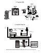
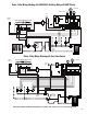
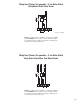

Typical Radiant Floor to Water Heater Installation
Cold
Supply
MIX
H
C
ASSE 1017
Tempering
Valve
Domestic
Hot
Supply
RADIANT
SYSTEM
(Secondary Side
of the System)
X-PUMP
BLOCK
Cold
Hot
WATER
HEATER
Check
Valve
Supply
Return
Exp.
Tank
Relief
Valve
Air
Separator
WARNING! A pressure relief valve and expansion tank must be installed on the secondary
side in addition to any pressure relief valve and expansion tank which is installed on primary
side of system. Use dedicated supply and return piping to the X-Pump Block from the water
heater so as not to add heated water into the house’s cold water pipin
g
.
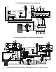
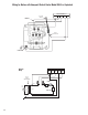
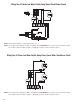
Typical Snow Melt Installation
SNOW MELT
SYSTEM
X-PUMP
BLOCK
Supply
Return
Exp.
Tank
Relief
Valve
Air
Separator
Exp.
Tank
Separator
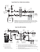
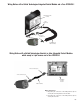
FIXED SPEED
CIRCULATOR
(4 PIN PLUG)
VARIABLE SPEED
CIRCULATOR
(3 PIN PLUG)
HEAT
SOURCE
(Tb)
(Ts)
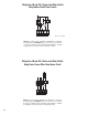
Note 1: There must be no more than 4 pipe diameters between the tees in the boiler and
system loops in order to prevent ghost flow when the variable speed injection
pump is off and either the boiler pump or system pump is on.
Note 2: There must be at least 6 pipe diameters of straight pipe on either side of the tees in
order to prevent the momentum of water in the boiler and system loops from pushing
flow through the injection loop.
Note 3: There should be a minimum 1 foot drop to create a thermal trap in order to prevent
convective heat transfer through the injection loop.
(
Δ
Ts)
{
Note 1 Note 2
Note 3
{
{
Note 3
{
Note 2
{
Note 1
}
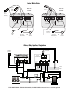
HEAT SOURCE
RETURN SENSOR
(OPTIONAL)
SYSTEM
SUPPLY
SENSOR
SYSTEM
RETURN
SENSOR
Tb = Boiler Supply Temperature
Ts = System Supply Temperature
ΔTs = System Temperature Drop
(typically 20°F for convectors
and 10°F for radiant floor heating)
61