
Specifications


91
TO: 120 VAC POWER
CIRCULATOR
POWER
T STAT
TO: "TT" on Boiler Aquastat
THERMOSTAT
TO: 120 VAC POWER
POWER
T STAT
TO: ZC on Boiler Control
TO: DHW Aquastat if PC700
Boiler Reset is installed.
CIRCULATOR
THERMOSTAT
TO: ZR on Boiler Control
NZCZRHHH
POWER
INPUT
120VAC
INPUT
120VAC
OUTPUT
CIRC
OUTPUT
PRIORITY
OUTPUT
END
SWITCH
RESET
OVERRIDE
THERMOSTATEXPANSION
END
SWITCH
RESET
OVERRIDE
THERMOSTATEXPANSION
X
COM
T/W
T/R
X1 12243
X
COM
T/W
T/R
X1 12243
JUMPER
SR 501-EXP
RESET
POWER
CONTROLS
FUSE
1 AMP
NORMAL
MODE
SR 501-EXP
RESET
POWER
CONTROLS
FUSE
1 AMP
NORMAL
MASTER
SLAVE
MODE
FUSE
5 AMP
TO: DHW Aquastat if PC700
Boiler Reset is installed.
T
T
K1-A
K1-B K2-A K2-A
K1 K2
NZCZRHHH
POWER
INPUT
120VAC
INPUT
120VAC
OUTPUT
CIRC
OUTPUT
PRIORITY
OUTPUT
MASTER
SLAVE
FUSE
5 AMP
K1-A
K1-B K2-A K2-A
K1 K2
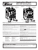
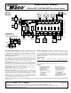
Operation: When the thermostat calls for heat, the appropriate circulator is ener-
gized and the isolated end switch (X and X) will start the boiler. Priority Output
has power all the time, except when the thermostat is calling.
Mode Operation: When the mode switch is set to NORMAL, the end switch
relay will be energized if any zone is in operation. When the switch is set to
RESET, the end switch relay will only be energized through the operation of a
plug-in reset control or closure of Priority Input.
Jumper Placement: The jumper should be placed between terminals ZC and H.
Connect the isolated end switch to the aquastat control on the boiler.
Power Input: Connect 120 volt ac power input to terminals N and H. Neutral
wire to terminal N. Hot wire to terminal H.
Expansion Connections: Set the expansion switch to MASTER on the switching
relay that has the designated priority zone or is utilizing the PowerPort options.
Set all other daisy chained controls to SLAVE. Connect thermostat wire (18-22
gauge) between terminals 1, 2, 3, 4 on the master control to the corresponding
1, 2, 3, 4 on the SLAVE control(s). Controls may be daisy chained up to 20 zones
using any combination of -EXP controls.
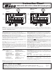
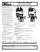
Operation: When the thermostat calls for heat, the appropriate circulator is ener-
gized when the boiler’s aquastat is above the set low limit. The ZR (120VAC) out-
put will signal the boiler to start. Priority Output has power all the time, except
when the thermostat is calling.
Mode Operation: When the mode switch is set to NORMAL, the end switch
relay will be energized if any zone is in operation. When the switch is set to
RESET, the end switch relay will only be energized through the operation of a
plug-in reset control or closure of Priority Input.
Jumper Placement: REMOVE
the jumper between terminals ZC and H. Connect
terminal ZC to ZC terminal on the aquastat control. Connect terminal ZR to ZR
terminal on the aquastat control. Confirm polarity is consistent between boiler
aquastat and switching relay.
Power Input: Connect 120 volt ac power input to terminals N and H. Neutral
wire to terminal N. Hot wire to terminal H.
Expansion Connections: Set the expansion switch to MASTER on the switching
relay that has the designated priority zone or is utilizing the PowerPort options.
Set all other daisy chained controls to SLAVE. Connect thermostat wire (18-22
gauge) between terminals 1, 2, 3, 4 on the master control to the corresponding
1, 2, 3, 4 on the SLAVE control(s). Controls may be daisy chained up to 20 zones
using any combination of -EXP controls.
External Diagnostics: Externally visible lights show full functionality of the
switching relay. The green light should always be on, indicating that power is
connected. When the thermostat calls for heat, both the appropriate circulator
and red indicating light are energized.
Warning: Wiring connections must be made in accordance with all applicable electrical codes. Use copper wire only with a minimum temperature rating of 60/75°C. Failure to follow this instruction can
result in personal injury or death and/or property damage. 12-18 gauge wire recommended for 120 VAC connections, 14-22 gauge wire for thermostat connections, and 14-22 gauge wire for 24 VAC source
connections.
Cold Start Boiler
Application
Tankless Coil Boiler
Application
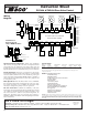
Specifications:
PRODUCT NUMBER POWER TRANSFORMER MAXIMUM DIMENSIONS OF ENCLOSURE
NUMBER OF ZONES CONTROLS VOLTAGE COMBINED LOAD WIDTH HEIGHT DEPTH
SR501-EXP 1 1 120 VAC Input 5.0 amps 4 1/4" 5 1/4" 2 3/4"
All Switching Relays are relay type DPDT, have a thermostat current of .18, and have a
single phase motor rating per zone of 1/3 hp (5.0A) @ 120 VAC.
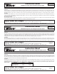
Instruction Sheet
SR501-EXP Switching Relay
Features: External Indicator Lights
Ideal for Retrofitting
Priority Output
Simplified Wiring
Add-On Power Controls
Sealed Relays
Compact Design
Fuse Protected
100% Factory Tested
Isolated End Switch
Expandable to 20 Zones
Contractor Friendly PC Board
Layout
Universal Thermostat
Compatibility
UL Approved
24 volt Power Input or Output
Terminal
Extended 3 Year Warranty
Made in the USA
Do it Once. Do it Right.
®
TACO, INC., 1160 Cranston Street, Cranston, RI 02920 Telephone: (401) 942-8000 FAX: (401) 942-2360.
TACO (Canada), Ltd., 6180 Ordan Drive, Mississauga, Ontario L5T 2B3. Telephone: 905/564-9422. FAX: 905/564-9436.
Visit our web site at: http://www.taco-hvac.com
Printed in USA
Copyright 2005
TACO, Inc.
Warning: When using Alternative Wiring diagram, wiring instructions must be followed so power originates from the boiler aquastat. Failure to
follow these wiring instructions may result in a secondary source of power being connected to the boiler that may activate it under certain cir-
cumstances, causing injury or death.