
Owner`s manual

VANNER
Incorporated OWNER’S MANUAL
PMEC-12/24 OWNER‟S MANUAL
15
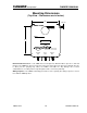
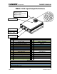
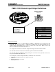
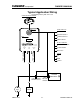
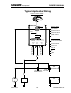
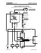
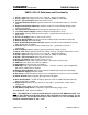
PMEC-12/24 Input/Output Definitions
Deutsch 33 Position Pin Assignments
Pin
Description
Pin
Description
1
CT12V – Low
18
CT24V – Sensor Gnd
2
CT12V – High
19
CT24V - +5V Supply
3
CT12V – Sensor Gnd
20
Hood Switch
4
Fast Idle (Remote Indicator)
21
CAN Low
5
Engine Start (Remote Indicator)
22
CAN Shield
6
12V Battery Temp Sensor Ground
23
CAN High
7
12V Battery Temp Sensor +5V Supply
24
Remote Switch Disable
8
Park Switch
25
+5V Remote Supply
9
CT12V - +5V Supply
26
Key Sense
10
Remote Switch Enable
27
Power Ground
11
Remote Ground
28
Power Ground
12
Auto Start Enabled (Remote Indicator)
29
Auto Start Enabled
13
Fast Idle
30
Engine Start
14
Sense Negative
31
Ignition (12V or 24V)
15
12V Battery Temp Sensor +12V
32
12V Battery Temp Sensor
16
CT24V – Low
33
+24V Sense
17
CT24V – High
Color Legend
12V Current Sensor Leads
Remote Leads
Voltage and Temperature Sensor Leads
24V Current Sensor Leads
CAN Communication Leads
Vehicle I/O
16
3
4
30
13
14
5
31
32
15
33 17
6
18
19
7
20
1
8
2
12
11
29
28
27
26
25
9
21
22
23
10
24
Deutsch HDP24-24-33PN
Mating Connector:
Deutsch HDP26-24-33SN
Mating Contacts:
Deutsch 1062-20-0122
Output A – 50A
5/16-18 Stud, Typ
Input – 100A
Output B – 50A
Green “Power” LED