
Technical data

31
Assembly
1
2a
2b
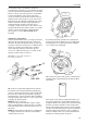
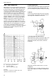
called soft shims, always being installed against the
block, must be replaced against new ones. Carefully
clean the contact surfaces between the block and the
fuel injection pumps and install shims with thickness
equal to the sum of the marking on the block and that
on the fuel injection pump, (4) earlier marking. Exam-
ple: The block has the marking 4 (= 4 tenths of a mil-
limeter /.015748 in.) The pump marking is 4 (= 4
tenths of a millimeter /.015748 in.) Total amount of
shims = 0.8 mm (.031496 in.) In this case select two
soft shims 0.2 and 0.3 mm (.011811 in.). Place the
hard shim between the two soft ones and install the
pump.
NOTE! Never install a hard shim together with another
hard shim or against the block or the fuel injection
pump.
Hard shims are available in thicknesses 0.3, 0.6 and
0.9 mm (.011811, .02362, .035433 in. respectively).
Soft shims are available in thicknesses 0.2 and 0.3
mm (.007874 and .011811 in.).
On later version engines an O-ring has been intro-
duced as a seal between the injection pump and the
block. Only so-called hard shims may be used on
these engines when shimming. Hard shims are avail-
able in thickness of 0.2 mm (0.0079 in), 0.3 mm
(0.0118 in), 0.6 mm (0.0024 in) and 0.9 mm (0.0354
in).
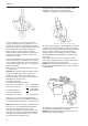
Injection setting in connection with new block or
camshaft
16. If the block or the camshaft are replaced the block
must be measured and marked, using the setting
disc p/n 884787 and a sliding calmer.
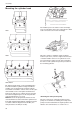
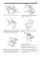
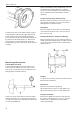
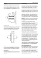
A. The setting-disc consists of two rings, an inner and
an outer. The inner ring determines the injection angle
and has markings (holes) for 20°, 22° and 23°. The in-
jection angle is fixed with a pin (1). When the injection
angle is set after block or camshaft replacement, the
setting tool should always be set to 22°. Using the
tool set to 22°, all injection angles can be adjusted, in-
cluding 16° and 18°, where there is no setting hole on
the tool.
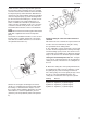
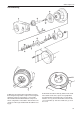
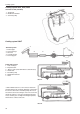
B. Mount the setting-disc on the pulley with two bolts,
do not tighten the bolts. Turn the setting-disc so that
the guide pin (2a) comes in the largest of the four
holes in the pulley. Press in the guide pin (2a) so that
the disc is centered and tighten the bolts. The
setting-disc is marked for each respective cylinder:
Marking Denotes
Cylinder 1 Cylinder 1 (1, 2 and 3 cylinder engines)
Cylinder 2/2 Cylinder 2 (2 cylinder engine)
Cylinder 2/3 Cylinder 2 (3 cylinder engine)
Cylinder 3/3 Cylinder 3 (3 cylinder engine)