OPERATOR’S MANUAL D1-13, D1-20, D1-30, D2-40
This operator’s manual is also available in the following languages: Diese Betriebsanleitung ist auch auf Deutsch erhältlich. Dit instructieboek kan worden besteld in het Nederlands. Ein Bestellcoupon ist am Ende der Betriebsanleitung zu finden. De bestelcoupon vindt u achter in het instructieboek. Ce manuel d’instructions peut être commandé en français. Denne instruktionsbog kan bestilles på dansk. Vous trouverez un bon de commande à la fin du manuel d’instructions.
Welcome aboard Volvo Penta marine engines are used all over the world today. They are used in all possible operating conditions for professional as well as leisure purposes. That’s not surprising. After more than 90 years as an engine manufacturer and after delivering over 500,000 marine engines, the Volvo Penta name has become a symbol of reliability, technical innovation, top of the range performance and long service life. We also believe that this is what you demand and expect of your Volvo Penta engine.
Contents Safety Information ............................................... 3–7 Maintenance schedule .................................... 25–26 Introduction ......................................................... 8–9 Running-in ............................................................ 8 Fuel and oil types ................................................ 8 Certified engines .................................................. 9 Warranty information ............................................
Safety Information Read this chapter carefully. It concerns your safety. This chapter describes how safety information is presented in the Operator's Manual and on the engine itself. It also gives a general account of basic safety precautions to be taken when operating the boat and maintaining the engine. Check that you have the correct Operator's Manual before you read on. If this is not the case please contact your Volvo Penta dealer.
Safety Information Safety precautions to be taken when operating the boat Your new boat Read Operator's Manuals and other information supplied with your new boat. Learn to operate the engine, controls and other equipment safely and correctly. If this is your first boat, or is a boat type with which you are not familiar, we recommend that you practice controlling the boat in peace and quiet.
Safety Information Carbon monoxide poisoning When a boat is moving forward backwash is caused behind the boat. Sometimes this backwash can be so powerful that exhaust gases can be sucked into the cabin or seating well on the boat with the resulting risk of carbon monoxide poisoning for those on boar d. The backwash problem is greatest with high, broad boats with a squared stern. But other types of boat can also have backwash problems under certain conditions, for example when running with an awning rigged.
Safety Information Safety precautions for maintenance and service operations Preparations Knowledge The Operator's Manual contains instructions on how to carry out general maintenance and service operations safely and correctly. Read the instructions carefully before starting work. Service literature covering more complicated operations is available from your Volvo Penta dealer.
Safety Information Hot surfaces and fluids There is always a risk of burns when working with a hot engine. Beware of hot surfaces. For example: the exhaust pipe, turbocharger (TC), oil pan, charge air pipe, starter element, hot coolant and hot oil in oil lines and hoses. Carbon monoxide poisoning Start the engine only in a well-ventilated area.
Introduction This Operator's Manual has been compiled to help you get the most from your Volvo Penta engine. It contains all the information you need in order to operate and maintain your engine safely and correctly. Please read the Operator's Manual carefully and learn how to operate the engine, controls and other equipment safely. Always have the Operator's Manual available. Keep it in a safe place and do not forget to give it to the new owner if you sell your boat.
Introduction Certified engines It is important to be aware of the following information if you own or run an engine that is exhaust emission certified: ● The engine must not be modified in any way except with accessories and service kits approved by Volvo Penta. Certification means that an engine type is inspected and approved by the authorities. The engine manufacturer guarantees that all engines manufactured of that type correspond to the certified engine.
Declaration of Conformity for Recreational Craft Propulsion Engines with the exhaust emission requirements of Directive 94/25/EC as amended by 2003/44/EC D1-13, D1-20, D1-30, D2-40 Engine manufacturer: Body for exhaust emission assessment: AB Volvo Penta Gropegårdsgatan 405 08 Göteborg Sweden NKIP Nipkowweg 9 Postbus 65 8500AB Joure Netherlands ID Number: 0613 Module used for exhaust emission assessment ........... B, EC Type Examination acc to Annex VII Other Community Directives applied .............
Identification number Your engine and transmission has identification plates with identification numbers. This information should always be quoted when ordering service and replacement parts. There are probably similar plates on your boat and its equipment. Make a note of the details below, make a copy of the page and keep it so that you have a copy should the boat be stolen. The appearance and location of identification plates is shown below.
Presentation 8 11 2 3 1 10 9 7 4 5 12 D1-20 with reverse gear MS10A 1 14 13 15 D1-20 with reverse gear MS10A 2 3 8 11 10 9 7 4 5 D1-30 with reverse gear MS15A 12 6 12 13 14 D1-30 with reverse gear MS15A 15
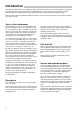
Presentation 1 2 8 3 9 10 11 7 15 4 5 17 12 13 14 16 18 19 D2-40 with sailing boat drive 130S 1. 2. 3. 4. 5. 6. 7. Coolant filler cap Heat exchanger Relay box with fuses Generator Starter motor Oil cooler, reverse gear Dipstick, reverse gear/S-drive 8. 9. 10. 11. 12. 13. 14. Air cleaner (ACL)/Air intake Dipstick, engine Oil filler cap, engine Fuel pump Oil filter Fuel filter Injection pump 20 D2-40 with sailing boat drive 130S 15. 16. 17. 18. 19. 20.
Instrumentation This chapter only describes the instrument panels available as standard alternatives for your engine from Volvo Penta. Note that in certain boats instruments, alarm panels, key switches etc. may be installed separately without the instrument panels shown here. If you want to install additional instrumentation, or your boat is equipped with instruments not described here, please contact your Volvo Penta dealer. Instrument panel with ignition switch 1 1.
Instrumentation S = The mechanical restart inhibitor is disengaged. The key springs back automatically to the 0 position. 0 = The key can be inserted and removed. I = Operating position. II = Glow plug position. The glow plugs are connected and pre-heating the engine. III = Start position. The starter motor is engaged. IMPORTANT! Read the starting instructions in the chapter: Starting the engine.
Instrumentation Warning display If the acoustic alarm sounds, one of the three warning lamps (13-15) on the instrument panel starts to flash to indicate the source of the alarm. 13. Engine coolant temperature too high. 14 15 13 16 IMPORTANT! If the alarm sounds: Reduce engine speed to idle (neutral). Stop the engine if the temperature does not drop. Investigate and correct the malfunction. 14. Low oil pressure. IMPORTANT! If the alarm sounds: Stop the engine immediately and investigate. 15.
Controls The shift function and engine speed control are combined in one lever. If necessary the shift function can be easily disengaged so that only the engine speed (rpm) is affected by the lever. The control lever has an adjustable friction brake. A neutral position switch is available as an accessory, this will only permit the engine to be started with the drive/reverse gear disengaged. Maneuvering Shifting and engine speed are controlled with the same lever (1). T T 1 N = Neutral position.
Starting the engine Make a habit of checking the engine and engine compartment visually before operating the boat. This will help you to quickly detect anything unusual that has or is about to happen. Also check that instruments and the warning display are indicating normal values when you have started the engine. Before starting ● Open the cooling water intake sea cock. ● Open fuel valve.
Starting the engine Starting. Instrument panel with ignition lock WARNING! Never use start spray or similar to start the engine. Danger of explosion! 1. If the engine is cold: Disconnect the gear shift function and move the control lever forwards to half throttle. WARNING! Make sure that the gear shift function is disconnected. If the engine is warm: Move the control lever to the neutral/idling position. 2. Insert the key in the ignition switch. Turn key to the ”I” position.
Starting the engine Starting. Instrument panel without ignition switch WARNING! Never use start spray or similar to start the engine. Danger of explosion! 1. If the engine is cold: Disconnect the gear shift function and move the control lever forwards to half throttle. WARNING! Make sure that the gear shift function is disconnected. If the engine is warm: Move the control lever to the neutral/idling position. 2. Activate the instrument panel by pressing the rocker switch downwards to ”Power ON/OFF”.
Starting the engine Starting using auxiliary batteries WARNING! Batteries produce oxyhydrogen. This gas is easily ignited and highly volatile. A shortcircuit, naked flame or spark can cause a large explosion. Ensure that the ventilation is good. Never mix up battery positive and negative terminals. This may cause sparks and an explosion. C B 1. Check the auxiliary batteries have the same rated voltage as the engine’s system voltage. 2.
Operation Avoid violent and unexpected changes in course and gear engagement. There is a risk that someone aboard will fall over or overboard. WARNING! A rotating propeller can cause serious injury. Check that nobody is in the water before engaging ahead or astern. Never drive near bathers or in areas where people could be in the water. Checking instruments 1 2 3 Check the instruments and warning display directly after starting the engine and then at regular intervals while driving the boat.
Operation Maneuvering 1. All shifting between ahead and astern must be done at engine idle speed. Shifting at higher speeds may damage the drive or reverse gear and will also be uncomfortable for those on board. 1. Reduce engine speed to idling and, if possible, let the boat lose most of its speed. 2. 2. Move the reverse gear control lever quickly and firmly into the neutral position. Wait for a moment. 3. 3. Move the gear control lever quickly and firmly into astern, then increase the speed.
Stopping the engine The engine should be run for a few minutes at idle (in neutral) before turning it off. This will avoid boiling and even out the temperature. This is especially important if the engine has been operated at high engine speeds and loads. Stopping If the instrument panel has an ignition switch the key should be turned to the stop position ”S”. The key will automatically spring back to the ”0” position when it is released and can then be removed.
Maintenance schedule Your Volvo Penta engine and associated equipment is designed to provide high operational reliability and long service life. They are constructed to withstand the marine environment while also affecting it as little as possible. Preventive maintenance in accordance with the maintenance schedule will ensure that it retains these qualities and avoid unnecessary operational disturbances.
Maintenance: Seawater system Every 200 operating hours or at least once a year, included in Extended Protection ● D1-13, D1-20, D1-30. Engine oil. Replace ......................................................page 30 ● D1-13, D1-20, D1-30. Oil filter. Replace .......................................................... page 30 ● Reverse gear. Oil change ............................................................................... page 48 ● Reverse gear. Lubricate propeller shaft seal. .....................
Maintenance This chapter contains instructions regarding how the above maintenance points should be carried out together with general technical information. Read the instructions carefully before starting work. Maintenance intervals are contained in the chapter above. Maintenance schedule WARNING! Read the safety precautions for maintenance and service in the chapter: Safety Precautions, before starting work.
Maintenance: Engine, general Drive belt. Check The belt drives both the circulation pump and the generator. A belt that is too loose can result in slippage, poor cooling and poor charging. A belt that is too tight can damage the bearings in the circulation pump and damage the generator. Check the tension of the belt regularly. Adjust as required. Check that the belt is not cracked or damaged. Replace a worn belt. Keep a spare belt onboard. 3 2 Drive belt.
Maintenance: Engine, general Air Cleaner (ACL). Changing Loosen the hose clamp (1) and screw (2) to remove the old filter. Fit the new filter and tighten the hose clamp. IMPORTANT! Take care that no contaminants enter the engine. 1 2 Idling. Adjustment For engine idling speed: Please refer to the Technical Data chapter. A lower engine speed can cause the engine to stall and a higher engine speeds can cause extra stresses to the drive/reverse when shifting.
Maintenance: Lubrication system Lubrication system IMPORTANT! With a new or reconditioned engine, the oil and oil filters must be changed after 20-50 hours of operation. After that they should be changed every 500 operating hours or at least once a year. Use only the recommended grades of oil: See the chapter ”Technical Data”. 2 Oil level. Checking and topping up The oil level should be within the marked area on the dipstick (1). It should be checked every day before the engine is started.
Maintenance: Freshwater system Freshwater system The fresh water system is the engines’ internal cooling system, which ensures that the engine operates at the correct temperature. It is a closed circuit system and must always be filled with a mixture of at least 40 % concentrated coolant and 60 % water to protect against internal corrosion, cavitation and damage caused by freezing.
Maintenance: Freshwater system Coolant. Mixture WARNING! All glycol is hazardous and harmful to the environment. Do not consume! Glycol is flammable. IMPORTANT! Ethylene glycol must not be mixed with other types of glycol. Mix: 40 % “Volvo Penta Coolant” (conc. coolant) 60 % water This mixture protects the engine against internal corrosion, cavitation and frost damage down to -28 °C (18°F). (Using 60 % glycol lowers the freezing point to -54 °C (65°F)).
Maintenance: Freshwater system Coolant level. Checking and topping up WARNING! Stop the engine and allow it to cool before opening the filler cap. Steam or hot coolant may spurt out. Hot coolant and hot surfaces can cause burns. Turn the filler cap slowly counter clockwise and let any pressure escape from the system before removing the cap. The coolant level should be between the MAX and MIN marking on the expansion tank, when the engine is cold. Top up coolant if necessary. Reinstall the filler cap.
Maintenance: Freshwater system Coolant. Draining Connect a hose to the engine drain cock(1) and another to the heat exchanger drain tap (2) and lower these into a vessel. Remove the filler cap on the heat exchanger to let the coolant run out faster. Open the drain cock (1) and the drain tap (2) and drain off all coolant. Before new coolant is put in, clean the heat exchanger as in the following paragraphs. NOTE! Deposit old coolant at a properly designated disposal site. 1 3 2 Heat exchanger.
Maintenance: Seawater system Seawater system The sea water system is the external cooling system of the engine. On engines with a stern drive, the sea water pump sucks in water via the drive, after which the water passes the sea water filter (optional extra) before it is pumped through the heat exchanger. Finally, the water is pumped out into the exhaust elbow pipe, where it is mixed with the exhaust gases.
Maintenance: Seawater system Vacuum valve. Cleaning Some engines have a vacuum valve installed in the seawater piping. WARNING! Risk for water penetration. Close the sea cock. Close the sea cock. Disassemble the valve. Unscrew the hexagonal cover. In the cover there is a membrane and a gasket. Clean all the parts. Turn the cover upside down. Install the membrane first and then the gasket. Turn the valve housing upside down as well. Screw the cover into position, but not too hard (0.
Maintenance: Seawater system Seawater system. Flush cleaning and corrosion inhibition When laying up during winter (or out of season), the seawater system must be flushed clean of all deposits and salt crystals. It must also be treated to protect against internal corrosion. 2 1 WARNING! Risk of water penetration. This work must be carried out with the boat on dry land. Approaching or working on a running engine is dangerous. Watch out for rotating components and hot surfaces.
Maintenance: Seawater system Seawater system. Draining If it is not possible to keep the engine compartment free of frost, the seawater system must be drained to prevent freezing damage. 8 2 5 Note that all the seawater must be drained. The type of drainage must be adapted to the way in which the engine is installed and any additional equipment that is connected, for example sea water filter (2), vacuum valve (8), exhaust riser with drain cock (9), silencer (7) etc.
Maintenance: Fuel system Fuel system All work on the engine injection pump or injectors must be carried out at an authorized workshop. Use only the recommended grade of fuel: See the chapter ”Technical Data”. WARNING! Fire risk. When carrying out work on the fuel system make sure the engine is cold. A fuel spill onto a hot surface or an electrical component can cause a fire. Store fuel soaked rags and other flammable material in fireproof conditions.
Maintenance: Fuel system Fuel filter. Changing Clean the filter mounting. To avoid fuel spills put a plastic bag over the filter before it is unscrewed. Unscrew the filter. Moisten the filter rubber gasket with a little oil. Screw on the new filter by hand until it is in contact with the mating surface. And then a further half turn but no more! Vent fuel system. Deposit the old filter at a properly designated disposal site. Start the engine and check for leaks.
Maintenance: Electrical system Electrical system WARNING! Always stop the engine and break the current using the main switches before working on the electrical system. Isolate shore current to the engine block heater, battery charger, or accessories mounted on the engine. Main switch The main switch must never be turned off before the engine has stopped. If the circuit between the generator and the battery is cut off when the engine is running the generator can be seriously damaged.
Maintenance: Electrical system Battery. Maintenance WARNING! Risk of fire and explosion. Never allow an open flame or electric sparks near the battery or batteries. WARNING! Never mix up battery positive and negative terminals. This may cause sparks and an explosion. WARNING! The battery electrolyte contains extremely corrosive sulfuric acid. Protect your skin and clothes when charging or handling batteries. Always use protective goggles and gloves.
Maintenance: Electrical system Battery. Charging WARNING! Danger of explosion! The batteries give off hydrogen gas during charging which when mixed with air can form an explosive gas oxyhydrogen A short-circuit, naked flame or spark can cause a large explosion. Ensure that the ventilation is good. WARNING! The battery electrolyte contains extremely corrosive sulfuric acid. Protect your skin and clothes when charging or handling batteries. Always use protective goggles and gloves.
Maintenance: Electrical system Electrical installations Leakage current from the electrical system can be caused by incorrect installation of electrical equipment. Leakage current can knock out the galvanic protection of components such as the drive, propeller, propeller shaft, rudder stock and keel and cause damage by electrolytic corrosion. IMPORTANT! Work on the boat’s low tension circuit should only be carried out by qualified or experienced persons.
Maintenance: Electrical system 5. If an auxiliary battery is in use, a main switch (D) should be connected between its + terminal and the fuse block. The main switch for the auxiliary battery must cut off all power consuming equipment connected to that battery and be turned off when power is no longer needed. All equipment connected to the auxiliary battery should have separate switches.
Maintenance: Electrical components diagram Electrical components diagram 1 3 2 1. Engine oolant temperature switch D1-13, D1-20 2. Engine oolant temperature switch D1-30, D2-40 3. Engine coolant temperature sensor 4. Alternator 5. Starter motor 6. Glow plugs 7. Engine speed sensor 8. Oil pressure switch 9.
Maintenance: S drive and reverse gear S drive and reverse gear The S drive and in certain cases the propeller (reverse gear) is equipped with a sacrificial anode which prevents galvanic corrosion. Faulty electrical installation can also cause the break down of the galvanic protection. Damage due to electrolytic corrosion occurs rapidly and is often extensive.
Maintenance: S drive and reverse gear Oil change. Reverse gear Remove the dipstick. Suck up oil using an oil pump through the hole for the dipstick. Measure out the correct amount of oil and fill up through the hole for the oil dipstick. For oil quality and capacity: See the chapter ”Technical Data”. IMPORTANT! Never overfill reverse gear. The oil level should always lie at the recommended level.
Maintenance: S drive and reverse gear Corrosion protection. Check Check the sacrificial anode (1) on the drive and the three sacrificial anodes (2) on the propeller. Replace with a new anode if 50% of the material has perished or at least once per season. IMPORTANT! Use zinc sacrificial anodes for salt water and magnesium anodes for freshwater. Remedy any paintwork damage on the drive according to the instruction in the chapter: Laying up / Launching. 1 2 Replacing sacrificial anodes 1.
Maintenance: S drive and reverse gear Removing 1. Set the control lever in the ”Ahead” position. A 2. Remove the propeller blade by first undoing the locking screws (5) completely and then pressing out the shaft studs (1). 1 6 3 4 3. Drive: Bend down the tabs of the tab washer (3) and remove the locking screw (4), tab washer and nut (6). Reverse gear: Remove the nut (7), washer (8) and then the locking screws (9). 4. Pull off the propeller hub and the spacing sleeve (drive).
Maintenance: S drive and reverse gear Propeller shaft seal. Reverse gear If the boat has a Volvo Penta shaft the shaft seal must be vented and lubricated directly after launching. Vent the bushing by pressing it together while pressing down on the shaft until water appears. Then press in approx. 1 cc water repellent grease into the seal. IMPORTANT! The seal must be replaced every 500 running hours or every 5th year. Rubber seal.
Laying up and launching Before taking the boat out of the water for winter/out-of-season storage have an authorized Volvo Penta workshop inspect the engine and other equipment. Inhibition should be carried out to ensure that the engine and transmission are not damaged while out of commission during the winter/off-season. It is important this is done properly and than nothing is forgotten. We have therefore provided a checklist covering the most important points.
Maintenance: Laying up and launching Bringing out of storage ● Check oil level in the engine and drive/reverse gear. Top up if necessary. If there is inhibiting oil in the system drain and fill with new oil, change oil filter. For correct oil grade: See the chapter ”Technical Data”. ● Drain the antifreeze from the seawater system. ● Install the impeller in the seawater pump (replace if the old one looks worn). ● Close/tighten drain cocks/plugs. ● Check drive belts.
Maintenance: Laying up and launching Painting the drive and underwater hull General Most countries have introduced legislation controlling the use of anti-fouling agents. In some cases these agents are completely forbidden for use on leisure craft. In these cases ask your Volvo Penta dealer for advice about alternative methods. IMPORTANT! Find out what regulations apply to the use of anti-fouling agents.
Fault-tracing A number of symptoms and possible reasons for engine problems are described in the table below. In case of faults or mishaps which you cannot solve, always contact the Volvo Penta dealership. WARNING! Read the safety precautions for maintenance and service in the chapter: Safety Information, before starting work.
Technical Data Engine model Engine model ........................................................... D1-13 Crankshaft power, kW (hp) ...................................... 9.0 (12.2) Propeller shaft power, kW (hp) ................................ 8.6 (11.8) D1-20 13.8 (18.8) 13.3 (18.0) D1-30 20.9 (28.4) 20.1 (27.3) D2-40 29.1 (39.6) 27.9 (38.0) D1-13 A 0.51(31) 2 67/72 (2.64/2.83) 23.5:1 2800-3200 850 ±25 Clockwise 20o 30o 96 kg D1-20 A 0.76 (46.5) 3 67/72 (2.64/2.83) 23.
Technical Data Electrical system System voltage ....................................................... Fuses ....................................................................... Battery capacity (starter battery) ............................ AC generator voltage/max. current ....................... output approx. ................................. Starter motor, output approx. .................................. 12 V 15A 70 Ah 14V/115A 1610 W 2.0 kW Reverse gear Type designation .......................
Notes ________________________________________________ ________________________________________________ ________________________________________________ ________________________________________________ ________________________________________________ ________________________________________________ ________________________________________________ ________________________________________________ ________________________________________________ ________________________________________________ ________________
Notes ________________________________________________ ________________________________________________ ________________________________________________ ________________________________________________ ________________________________________________ ________________________________________________ ________________________________________________ ________________________________________________ ________________________________________________ ________________________________________________ ________________
Notes ________________________________________________ ________________________________________________ ________________________________________________ ________________________________________________ ________________________________________________ ________________________________________________ ________________________________________________ ________________________________________________ ________________________________________________ ________________________________________________ ________________
✂ Yes please, I would like an operator’s manual in English at no charge. Orders can also be placed via the Internet: http://www.volvopenta.com/ manual/coupon Publication number: 774 5857 42200/615001/155099900192 Post or fax this coupon to: Document & Distribution Center Order Department ARU2, Dept. 64620 SE-405 08 Göteborg Sweden Fax: +46 31 545 772 Name Address Country NB! This offer is valid for a period of 12 months from delivery of the boat.
✂ Sí gracias, deseo recibir gratuitamente un libro de instrucciones en español. El pedido puede hacerse también por internet: http://www.volvopenta.com/ manual/coupon Número de publicación: 774 4849 42200/615001/155099900192 Franquear o enviar fax a: Document & Distribution Center Order Department ARU2, Dept.
✂ Ja graag, Ik wil kosteloos een instructieboek in het Nederlands ontvangen. U kunt ook bestellen via internet: http://www.volvopenta.com/ manual/coupon Publicatienummer: 774 4854 42200/615001/155099900192 Stuur of fax de coupon naar: Document & Distribution Center Order Department ARU2, Dept. 64620 SE-405 08 Göteborg Zweden Fax: +46 31 545 772 Naam Adres Land Denk eraan dat het aanbod geldt gedurende 12 maanden na de datum waarop de boot werd afgeleverd, daarna alleen indien nog verkrijgbaar.
✂ Sim, obrigado(a)! Gostaria de receber gratuitamente um manual de instruções em português. A encomenda também pode ser feita através da Internet: http://www.volvopenta.com/ manual/coupon Número de publicação: 774 4855 42200/615001/155099900192 Envie o talão pelo correio ou um fax para: Document & Distribution Center Order Department ARU2, Dept.
7745857 English 01-2006