Ford 4 Must ang .6L 1999 Cobr -200 a 1 DO / 2 Sup 0 0 HC 3-20 Inst ercha 1999 0 alla r 4 Ma MO 2001 tion ger Sys -2003 DEL YEAR ch 1 Inst tem - 50 S MOD EL YE * 200 4 Mo dels l egal i n Cal iforni a tate S ruct ions 50 St mog Lega ate S l p e rC mo * 200 4 Mo g Legal p ARB EO # Ddel Y er CA ear RB EO 213-17 #D-2 13-20 AR - only f o r raci ng ve hicles which m ay ne v er be u sed u p on a highw ay.
FOREWORD Proper installation of this supercharger kit requires general automotive mechanic knowledge and experience. Please browse through each step of this instruction manual prior to beginning the installation to determine if you should refer the job to a professional installer/technician. Please call Vortech Engineering for possible installers in your area. © 2004 VORTECH ENGINEERING, LLC All rights reserved.
TABLE OF CONTENTS FOREWORD .......................................................................................................................ii TABLE OF CONTENTS ......................................................................................................iii IMPORTANT NOTES ..........................................................................................................iv TOOLS AND SUPPLY REQUIREMENTS...........................................................................
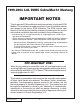
1999-2004 4.6L DOHC Cobra/Mach 1 Mustang IMPORTANT NOTES This kit requires ECM modification and the installation of a Vortech ECM Module. The modules are made specifically for each individual vehicle with respect to the factory ECM calibration. The ECM must be sent directly to Vortech by the installing customer (the charge for this service with module installation has been included in the purchase price).
1999-2004 FORD 4.6L DOHC COBRA/MACH 1 MUSTANG Installation Instructions CARB E0 #D-213-17 / CARB E0 #D-213-20 (Except 2004 Models) Congratulations on selecting the best performing and best backed automotive supercharger available today... the VORTECH® V-2 ® supercharger! Before beginning this installation, please read through this entire instruction booklet and the Street Supercharger System Owner's Manual which includes the Limited Warranty Program and the Warranty Registration form.
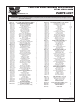
1999 4.6L DOHC Mustang Part No. 4FR218-010SQ ® PARTS LIST ENGINEERING, LLC IMPORTANT: Before beginning installation, verify that all parts are included in the kit. Report any shortages or damaged parts immediately. Part Number Description 2E229-160 V-2 E-TRIM SUPERCHARGER ASSEMBLY 4FR111-021 '99 MOUNTING BRACKET ASSEMBLY 7A375-178 3/8-16 x 1-3/4” HXHD G8 7K375-040 3/8” AN960 Flat Washers 7K312-001 5/16" AN Washers 2A046-113 Belt, K061130-Gates 4.
1999 4.6L DOHC Mustang w/aftercooler Part No. 4FR218-020SQ ® PARTS LIST ENGINEERING, LLC IMPORTANT: Before beginning installation, verify that all parts are included in the kit. Report any shortages or damaged parts immediately. Part Number Description Quantity 2E229-170 V-2 SC-TRIM SUPERCHARGER ASSEMBLY 4FR111-021 '99 MOUNTING BRACKET ASSEMBLY 7A375-178 3/8-16 x 1-3/4” HXHD G8 7K375-040 3/8” AN960 Flat Washers 7K312-001 5/16" AN Washers 2A046-113 Belt, K061130-Gates 4.
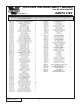
2001 4.6L DOHC Mustang Part No. 4FR218-030SQ ® PARTS LIST ENGINEERING, LLC IMPORTANT: Before beginning installation, verify that all parts are included in the kit. Report any shortages or damaged parts immediately. Part Number Description Quantity 2E229-160 V-2 E-TRIM SUPERCHARGER ASSEMBLY 1 4FR111-031 '01 4V MOUNTING BRACKET ASSEMBLY 1 7A375-178 3/8-16 x 1-3/4 HXHD G8 3 7K375-040 3/8 AN960 Flat Washer Plated 6 7K312-001 5/16 AN-Washer 14 4FR011-021 Mach.
2001 4.6L DOHC Mustang w/aftercooler Part No. 4FR218-040SQ ® PARTS LIST ENGINEERING, LLC IMPORTANT: Before beginning installation, verify that all parts are included in the kit. Report any shortages or damaged parts immediately. Part Number Description Quantity 2E229-170 V-2 SC-TRIM SUPERCHARGER ASSEMBLY 4FR111-031 '01 4V MOUNTING BRACKET ASSEMBLY 7A375-178 3/8-16 x 1-3/4 HXHD G8 7K375-040 3/8 AN960 Flat Washer Plated 7K312-001 5/16 AN-Washer 4FR011-021 Mach.
2003-2004 4.6L DOHC Mach 1 Mustang Part No. 4FR218-080SQ ® PARTS LIST ENGINEERING, LLC IMPORTANT: Before beginning installation, verify that all parts are included in the kit. Report any shortages or damaged parts immediately. Part Number Description Quantity 4FR111-041 '03 MACH 1 MNTG BRACKET ASSEMBLY 1 7A375-178 3/8-16 x 1-3/4 HXHD G8 3 7K375-040 3/8 AN960 Flat Washer Plated 6 7K312-001 5/16 AN-Washer 14 4FR011-021 Mach. Mtg Bkt, '01 4V 1 7J312-875 5/16" Washer, Custom 1 7C080-065 8mm x 1.
2003-2004 4.6L DOHC Mach 1 ® PARTS LIST ENGINEERING, LLC IMPORTANT: Before beginning installation, verify that all parts are included in the kit. Report any shortages or damaged parts immediately. Part Number Description Quantity Part Number 2E229-200 V-2 SC - TRIM 1 4FR111-041 '03 MACH 1MNTNG BRACKET ASSEMBLY 1 7A375-178 3/8-16 x 1-3/4 HXHD G8 3 7K375-040 3/8 AN960 Flat Washer Plated 6 7K312-001 5/16 AN-Washer 14 4FR011-021 Mach. Mtg Bkt, '01 4V 1 7J312-875 5/16" Washer, Custom 1 7C080-065 8mm x 1.
This Page Left Intentionally Blank P/N: 4FR020-010 ©2004 Vortech Engineering, LLC All Rights Reserved, Intl. Copr. Secured 23AUG04 86-93 4V Mus. Cobra(4FR v3.
1. PREPARATION/REMOVAL A. Disconnect the negative battery cable. B. Loosen the water pump pulley bolts. C. Remove the accessory drive belt. NOTE: The supplied 8mm x 16 bolt can be threaded into the spring tensioner idler hole to remove the accessory drive belt. D. Remove the "question mark" shaped crankcase vent hose with attached fittings from between the passenger side valve cover and the air inlet. E.
2. OIL DRAIN A. To provide an oil drain for the supercharger, it is necessary to make a hole in the oil pan. Locate and mark the hole per Fig. 2-a. The drain hole must be punched rather than drilled. B. Remove the paint around the hole area. C. Use a small center punch to perforate the pan and expand hole. Switch to a larger diameter punch and expand the hole further to approximately 9/16" diameter.
3. OIL FEED A. Remove the 1/4" NPT socket head plug located perpendicular to and directly beneath the factory oil pressure sending unit. This is found on the engine's driver's side below the oil filter. B. Thread the supplied 1/4" NPT #4 flare x 90° fitting into the pressure sending unit mount using engine oil on the pipe threads (see Fig. 3-a).
4. FUEL PUMP INSTALLATION, cont'd. J. Using the supplied fuel pump, reassemble the fuel pump assembly and canister with cap. K. Reinstall the canister assembly into the fuel tank and reattach the electrical connections. L. Reinstall the fuel tank, reconnect the fuel filter inlet line, reattach the fuel filler neck and reinstall the fuel cap. M. Turn the ignition key on and check the fuel pump for leaks. 5. FUEL INJECTOR REPLACEMENT A.
6. AIR CONDITIONING LINE MODIFICATION NOTE: Air conditioning lines are under high pressure and the fluid is highly toxic. Therefore, use extreme caution when bending the line to avoid kinking or breaking the line. Support the assembly as much as possible while bending for clearance. A. Carefully bend the high pressure air conditioning line (the line with the pressure port and cap) so that the pressure port rotates down (for supercharger inlet clearance). (See Fig. 6-a.) Fig. 6-a 7.
8. MAIN BRACKET ASSEMBLY/DRIVE BELT A. Attach the supplied 1/8" NPT x 45° flare fitting and oil feed hose to the oil feed fitting on the supercharger. Rotate the fitting so that it points forward, toward the volute side of the supercharger, perpendicular to the front cover. When tightening fitting, use a 1/2" wrench on the oil feed base for support. WARNING: When threading the 1/8" NPT x 45° flare fitting into the supercharger, use engine oil on the pipe threads for lubrication.
8.1 MAIN BRACKET ASSEMBLY/DRIVE BELT - 1999 Models A. Remove the three timing cover bolts, fixed idler pulley bolt (replace the factory idler pulley bolt with the supplied 8mm x 16 bolt and heavy duty washer) and passenger's side alternator mounting bolt from the front of the engine. Remove the upper bolt/stud located on the factory belt tensioner and replace with the supplied 8mm x 25mm bolt and washer. Remove the middle bolt also located on the belt tensioner. (See Fig. 8.1-a.) B.
P/N: 4FR020-010 ©2004 Vortech Engineering, LLC All Rights Reserved, Intl. Copr. Secured 23AUG04 86-93 4V Mus. Cobra(4FR v3.1) 8 A/C LINE SILENCER BRACKET VIEW A 1/2” VORTECH MOUNTING BRACKET 8mm X 140 BOLT AND WASHER ENLARGE TO 11/32" 8mm X 70 BOLT AND WASHER SANDWICH TABS BETWEEN ENGINE FRONT COVER AND SUPERCHARGER BRACKET Fig. 8.1-b 1/2” REMOVE THE SHADED AREA FOR SUPERCHARGER MOUNTING BRACKET CLEARANCE #2 Fig. 8.
8.1 MAIN BRACKET ASSEMBLY/DRIVE BELT - 1999 Models, cont'd. E. Loosen and remove the three nuts securing the factory coolant reservoir to the car. Temporarily move aside to provide room to mount the supercharger. (Do not remove any hoses or connectors from reservoir.) F. Remove the factory flanged water pump pulley and replace with the supplied non-flanged pulley. G. Following Figs. 8.1-c & 8.
8.1 MAIN BRACKET ASSEMBLY/DRIVE BELT - 1999 Models, cont'd. H. After the bracket has been fully secured (the belt should be properly routed around/under all pulleys except for the water pump), use a 1/2" breaker bar or ratchet to release the belt tension. Push the belt over the top radius of the water pump pulley, underneath the crank pulley, over the top of the tensioner pulley and release the tensioner (see Fig. 8.1-e). I. Route the oil drain hose down to the oil pan tube previously installed.
8.2 MAIN BRACKET ASSEMBLY/DRIVE BELT - 2001-2004 Models, cont'd. A. Remove the three timing cover bolts, IMPORTANT: It is imperative that the tenfixed idler pulley bolt (replace the facsioner does not get overloaded tory idler with the supplied Vortech when being pulled down durcomposite idler) and passenger's side ing belt installation. Bending of alternator mounting bolt from the front the tensioner may cause belt of the engine. (See Fig. 8.2-a.
8.2 MAIN BRACKET ASSEMBLY/DRIVE BELT - 2001-2004 Models 2001-2004 2001 ONLYONLY 5/16-18 x 1.75 SCREWS w/WASHERS 3/8-16 x 1.00 SCREW 2A017-016 BEARING PILOT ALTERNATOR BRACKET 2 8mm STUD (THREAD THE END WITH THE LEAST NUMBER OF THREADS INTO THE BLOCK UNTIL THE THREADS STOP) RELOCATED FACTORY IDLER (open side must face toward the alternator) ALTERNATOR BRACKET 1 5/16-18 x 1.00 SCREW w/WASHER SPACER IDLER ASSEMBLY SECTION VIEW OF VORTECH MOUNTING BRACKET WASHER 8mm NUT Fig. 8.
8.2 MAIN BRACKET ASSEMBLY/DRIVE BELT - 2001-2004 Models, cont'd. INSTALL SUPPLIED COMPOSITE IDLER USING FACTORY HARDWARE ROUTE BELT BEFORE INSTALLING BRACKETRY Fig 8.2-d / Step 1 ALTERNATOR BRACKET AND SPACER SUPPLIED STUD (THREADED TIGHTLY INTO BLOCK W/SHORT THREADED END) Fig 8.2-e / Step 2 Fig 8.2-f / Step 3 - Install supercharger/bracket assembly as shown 13 P/N: 4FR020-010 ©2004 Vortech Engineering, LLC All Rights Reserved, Intl. Copr. Secured 23AUG04 86-93 4V Mus. Cobra(4FR v3.
8.2 MAIN BRACKET ASSEMBLY/DRIVE BELT - 2001-2004 Models, cont'd. Fig. 8.2-g / Step 4 - Install alternator bracket 2 with idler plate assembly 5/16-18 x 1.75 BOLTS/WASHERS LOOSELY INSTALLED Fig. 8.2-h / Step 5 INSTALL w/"OPEN" SIDE TOWARD ENGINE BEARING PILOT WASHER (STEP FITS INTO BEARING BORE) Fig. 8.2-i / Step 6 P/N: 4FR020-010 ©2004 Vortech Engineering, LLC All Rights Reserved, Intl. Copr. Secured 23AUG04 86-93 4V Mus. Cobra(4FR v3.
8.2 MAIN BRACKET ASSEMBLY/DRIVE BELT - 2001-2004 Models, cont'd. M8 NUT w/ WASHER ROUTE BELT AS SHOWN Fig. 8.2-j / Step 7 PLACE ALTERNATOR DOWN ONTO THE 5/16-18 SCREWS AND SECURE (MAKE SURE THE WASHERS ARE PROPERLY LOCATED UNDER SCREW HEADS) Fig. 8.2-k / Step 8 - Complete tightening hardware SECURE BRACKETRY USING SUPPLIED M6 x 1.00 x 75 SCREWS W/WASHERS SUPPLIED SPACER (ONE EACH SIDE) Fig. 8.
P/N: 4FR020-010 ©2004 Vortech Engineering, LLC All Rights Reserved, Intl. Copr. Secured 23AUG04 86-93 4V Mus. Cobra(4FR v3.1) 8MM x 140 BOLT AND WASHER A/C CANISTER BRACKET 8MM X 70 BOLT AND WASHER VORTECH MOUNTING BRACKET 16 Fig. 8.2-m OIL DRAIN HOSE MOUNTING LOCATION FOR A/C CANISTER IDLER RELOCATION ASSEMBLY RELOCATED STOCK IDLER 2001-2004 Only 8MM THREADED STUD, WASHER AND NUT ALTERNATOR 8.2 MAIN BRACKET ASSEMBLY/DRIVE BELT - 2001-2004 Models, cont'd.
8.2 MAIN BRACKET ASSEMBLY/DRIVE BELT - 2001-2004 Models, cont'd. BELT ROUTING RELOCATED ALTERNATOR PULLEY SUPERCHARGER PULLEY 2001-2004 Only RELOCATED FACTORY IDLER VORTECH SUPPLIED IDLER WATER PUMP TENSIONER FACTORY IDLER POWER STEERING CRANK A/C Fig. 8.2-n 17 P/N: 4FR020-010 ©2004 Vortech Engineering, LLC All Rights Reserved, Intl. Copr. Secured 23AUG04 86-93 4V Mus. Cobra(4FR v3.
9. RADIATOR HOSE/WATER TUBE A. Remove the upper radiator hose from the radiator and modify (cut) as shown in Fig. 9-b on page 19. B. With the lower radiator hose still connected to the radiator, remove 2" from the end previously connected to the factory water tube. Set the 2" section aside. C. Following Fig. 9-c on page 19, pre-assemble the Vortech supplied "L" and "U" bent water tubes using the 2" hose (section removed in the previous step) and the supplied #20 clamps.
9. RADIATOR HOSE/COOLANT TUBE, cont'd. ENGINE 4-3/4" DISCARD UPPER RADIATOR HOSE (STOCK) CUT Fig. 9-b RADIATOR Mach 1 Models Only: Place .28" spacers under tabs TOP VIEW "L" BEND ASSEMBLY COOLANT TEMPERATURE SENSOR (UNDERSIDE OF TUBE) WATER FILL/AIR PURGE (3/8" NPT PLUG) SUPPLIED #20 CLAMPS (3X) "U" BEND ASSEMBLY 2" WIDE HOSE REMOVED FROM THE TOP END OF THE LOWER FACTORY RADIATOR HOSE VORTECH WATER TUBE ASSEMBLY UPPER RADIATOR HOSE CONNECTION LOWER RADIATOR HOSE CONNECTION Fig.
10. AIR INLET A. Using the supplied 1/4-20 hardware, mount the supplied MAF meter to the Vortech MAF bracket and secure (see Fig. 10-a for orientation). Remove the factory MAF screen before attaching the meter to the new MAF bracket. B. Attach the supplied K & N air filter, 4" sleeve, 90° x 3-1/2" x 4" elbow and #64 hose clamps to the MAF and secure. C. Mach 1 Models Only: Cut the outer two wires attached to the MAF harness plug approximately 2" from the MAF connector. (See Fig. 10-h.
BYPASS VALVE 3” x Ø1” HOSE (TRIM TO FIT) TO DISCHARGE TUBE 21 STRAIGHT FITTING INLET DUCT Fig. 10-c #16 HOSE CLAMPS 1” UNION Ø1” x 90° ELBOW TO 1” FITTING ON INLET DUCT 8” x Ø1” HOSE (TRIM TO FIT) TO MANIFOLD PRESSURE/VACUUM VIEW FROM FRONT OF VEHICLE 1999-2004 4V FORD MUSTANG AFTERCOOLED AND NON-AFTERCOOLED AIR INLET/BYPASS ASSEMBLY 10. AIR INLET, cont'd. P/N: 4FR020-010 ©2004 Vortech Engineering, LLC All Rights Reserved, Intl. Copr. Secured 23AUG04 86-93 4V Mus. Cobra(4FR v3.
P/N: 4FR020-010 ©2004 Vortech Engineering, LLC All Rights Reserved, Intl. Copr. Secured 23AUG04 86-93 4V Mus. Cobra(4FR v3.1) 22 HOSE CONNECTS TO INLET DUCT Fig. 10-d RIGHT SIDE VALVE COVER BREATHER VORTECH SUPPLIED 3/4" PLASTIC ELBOW INSERTED INTO VALVE COVER 3/4" HOSE TRIM TO FIT FRONT OF VEHICLE 10. AIR INLET, cont'd.
10. AIR INLET, cont'd. M. (Mach 1 Models Only): 1. Remove the factory plastic PCV tube from the driver side of the engine and discard. Insert the large end of the supplied PCV valve into the factory rubber PCV elbow attached to the rear of the driver's side valve cover. Attach the supplied 5/8" bent tube to the intake manifold port previously connected to the plastic PCV tube using the supplied short length of 5/8" hose, 3/8" hose piece and the brass 3/8" to 5/8" reducer as shown. (See Figs. 10-e, 10-f.
10. AIR INLET, cont'd. GRAY w/RED STRIPE WIRE CONNECT TO RED AIR TEMP SENSOR WIRE GRAY WIRE CONNECT TO THE BLACK/BROWN AIR TEMP SENSOR WIRE RED BLACK/BROWN SUPPLIED IAT SENSOR CONNECTOR CUT TWO OUTER WIRES HERE LEAVE APPROX. 2" OF WIRE ATTACHED TO PLUG MAF PLUG Fig. 10-h / MAF Modifications (Mach 1 Models Only) P/N: 4FR020-010 ©2004 Vortech Engineering, LLC All Rights Reserved, Intl. Copr. Secured 23AUG04 86-93 4V Mus. Cobra(4FR v3.
10. AIR INLET, cont'd 3. Modify the steel air scoop base mount as shown. (See Figs. 10-i, 10-j.) A bandsaw is the best tool to use. An abrasive cut-off wheel or hacksaw may also be used. 4. Temporarily place the modified steel air scoop base into its factory location on top of the intake manifold. Loosely install the two factory screws that secure the rear of the bracket to the intake manifold (do not tighten at this time).
10. AIR INLET, cont'd Referring to Figs. 10-k, 10-l, attach the driver's side relocation bracket to the alternator and the underside of the modified steel air scoop base and align. Mark and drill two 5/16" holes in the modified scoop base. Permanently attach the relocation bracket to the modified steel air scoop base using the 1/4-20 x .75 screws, nuts and washers. 5. Remove the front passenger's side intake manifold cover bolt. (See Fig. 10-m.
AFTERCOOLER KITS ONLY: If an aftercooler kit is being installed, please substitute the supplied "Maxflow Power Cooler" instructions in place of step 11. Resume at step 12 after the completion of the Aftercooler installation. 11. SUPERCHARGER DISCHARGE A. Slide the 4-1/2" diameter sleeve and #72 hose clamps onto the throttle body. Slide the 2-3/4" sleeve and #44 hose clamps onto the supercharger discharge. B.
12. ECM MODULE INSTALLATION NOTE: When the ECM is sent, the following step will be performed by Vortech to ensure proper cleaning and module installation. (Step 12 is for reference only.) A. Double check that the battery cable is disconnected from the vehicle. B. Remove the passenger side front kickpanel from the interior of the vehicle. Remove the sound deadening material (if any) that is covering the ECM. Remove the plastic ECM hold-down bracket. C.
WARNING: Do not attempt to operate the vehicle until ALL components are installed and ALL operations are completed including the final check. 13. FINAL CHECK NOTE: Once the ECM is recieved back from Vortech with the ECM module installed, reinstall the ECM into the vehicle. In some cases, the extra height of the ECM module will not allow the use of the factory hold-down bracket. Reconnect the factory harness and reinstall the factory kick panel. A. Reconnect the battery. B.
® ENGINEERING, LLC 1650 PACIFIC AVENUE • CHANNEL ISLANDS, CA 93033-9901 • (805) 247-0226 P/N: 4FR020-010 ©2004 Vortech Engineering, LLC All Rights Reserved, Intl. Copr. Secured 23AUG04 86-93 4V Mus. Cobra(4FR v3.