
Manual

P/N: 4FR020-010
©2004 Vortech Engineering, LLC
All Rights Reserved, Intl. Copr. Secured
23AUG04 86-93 4V Mus. Cobra(4FR v3.1)
P/N: 4FR020-010
©2004 Vortech Engineering, LLC
All Rights Reserved, Intl. Copr. Secured
23AUG04 86-93 4V Mus. Cobra(4FR v3.1)
28
A. Double check that the battery cable is disconnected
from the vehicle.
B. Remove the passenger side front kickpanel from
the interior of the vehicle. Remove the sound
deadening material (if any) that is covering
the ECM. Remove the plastic ECM hold-down
bracket.
C. Using a 10mm socket or wrench, remove the
harness and plug from the ECM (as you loosen
the bolt, the connector will slowly release).
Remove the ECM from the vehicle.
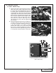
D. Gently remove the plastic service port cover on the
opposite end from the main harness connection.
The main circuit board with a double sided
electrical edge connector will now be exposed
(see Fig. 12-a).
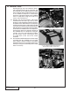
E. Using alcohol and a cotton swab, carefully clean
the grease off of both sides of the main circuit
board service contacts.
F. Using a sharp knife, small at screwdriver or
scraper, gently scrape the remaining thin layer
of silicone off of the contacts. This can easily
be done by removing the corner screws on the
ECM and opening the cover to better expose
the connector to be cleaned. DO NOT remove
or damage the electrical contacts. If the silver
contacts start to give off ne metal shavings, you
are done. STOP. It is extremely important that
all of the silicone be removed from the contacts.
If the surface is not completely clean, the
vehicle may not start or run properly. If the ECM
cover was removed, reinstall it at this time.
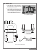
G. With the ECM service port contacts now clean,
you are ready to install the ECM module. Align
the module with the ECM (see Figs. 12-b,
12-c). Slide the module onto the ECM by applying
gentle pressure evenly. Apply the supplied section
of adhesive tape to the top of the ECM and module
to resist movement from vibration.
H. Reinstall the ECM into the vehicle. In some cases,
the extra height of the ECM module will not allow
the use of the factory ECM bracket. Reconnect
the factory harness and reinstall the factory kick
panel.
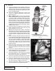
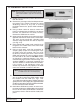
Fig. 12-a / ECM & Module Alignment
Fig. 12-b / Proper Module Installation
Fig. 12-c / Improper Module Installation
NOTE: Improper contact cleaning is the largest rea-
son ECM modules fail or work improperly.
NOTE: When the ECM is sent, the following step will be
performed by Vortech to ensure proper cleaning
and module installation. (Step 12 is for reference
only.)
12. ECM MODULE INSTALLATION