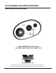
2010 CAMARO COG DRIVE UPGRADE Installation Instructions 2010 CAMARO SS (LS3 & L99) P/N: 4GE118-010, 4GE118-020, 4GE118-030 ® ENGINEERING, LLC 1650 Pacific Avenue, Channel Islands, CA 93033-9901 • Phone 805 247-0226 Fax: 805 247-0669 • www.vortechsuperchargers.
FOREWORD This manual provides information on the installation, maintenance and service of the Vortech supercharger kit expressly designed for this vehicle. All information, illustrations and specifications contained herein are based on the latest product information available at the time of this publication. Changes to the manual may be made at any time without notice.
TABLE OF CONTENTS FORWORD . . . . . . . . . . . . . . . . . . . . . . . . . . . . . . . . . . . . . . . . . . . . . . . . . . . . . . . . . . . . . . . ii TABLE OF CONTENTS . . . . . . . . . . . . . . . . . . . . . . . . . . . . . . . . . . . . . . . . . . . . . . . . . . . . iii TOOL & SUPPLY REQUIREMENTS . . . . . . . . . . . . . . . . . . . . . . . . . . . . . . . . . . . . . . . . iv PARTS LIST 75T/30T (4ge118-010) . . . . . . . . . . . . . . . . . . . . . . . . . . . . . . . . . . . . . . .
Vortech 50MM COG DRIVE UPGRADE Installation Instructions 2010 CHEVROLET CAMARO SS Before beginning this installation, please read through this entire instruction booklet The Vortech 2010 Camaro 50mm cog drive upgrade was designed specifically for use on 2010 Chevrolet Camaro SS vehicles equipped with a supercharger to support applications with increased horsepower over the basic kit. As with any power enhancing product, this unit is intended for use on healthy, well-maintained engines.
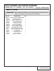
2010 CAMARO COG DRIVE UPGRADE 50MM COG, 75T CRANK / 30T S/C PULLEY PARTS LIST Part No. 4GE118-010 IMPORTANT: Before beginning installation, verify that all parts are included in the kit. Report any shortages or damaged parts immediately. PART NO. DESCRIPTION 4GE118-010 DRIVE ASSY, 75T/30T COG 50MM UPGRADE 7B500-325 ARBOR, S/C TENS PLY 7PA375-500 SCREW, IDLER ADJUST, 5.
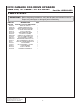
2010 CAMARO COG DRIVE UPGRADE 50MM COG, 75T CRANK / 32T S/C PULLEY PARTS LIST Part No. 4GE118-020 IMPORTANT: Before beginning installation, verify that all parts are included in the kit. Report any shortages or damaged parts immediately. PART NO. DESCRIPTION 4GE118-020 DRIVE ASSY, 75T/32T COG 50MM UPGRADE 7B500-325 ARBOR, S/C TENS PLY 7PA375-500 SCREW, IDLER ADJUST, 5.
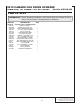
2010 CAMARO COG DRIVE UPGRADE 50MM COG, 75T CRANK / 34T S/C PULLEY PARTS LIST Part No. 4GE118-030 IMPORTANT: Before beginning installation, verify that all parts are included in the kit. Report any shortages or damaged parts immediately. PART NO. DESCRIPTION 4GE118-030 DRIVE ASSY, 75T/34T COG 50MM UPGRADE 7B500-325 ARBOR, S/C TENS PLY 7PA375-500 SCREW, IDLER ADJUST, 5.
This page intentionally left blank DP/N: 007123v1.0 © 2010 Vortech Engineering, LLC All Rights Reserved, Intl. Copr. Secured.
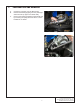
1. PREPARATION AND REMOVAL A. Unplug the connector from the MAF sensor. B. Remove the discharge piping from the passenger side intercooler up pipe to the throttle body. C. Remove the existing serpentine supercharger belt by loosening the spring tensioner with a ½” drive breaker bar or ratchet. Fig. 1-a Fig. 1-b 1 DP/N: 007123v1.0 © 2010 Vortech Engineering, LLC All Rights Reserved, Intl. Copr. Secured.
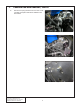
1. D. PREPARATION AND REMOVAL, cont’d Remove the spring tensioner from the front mounting plate and replace with M10X1.5X55mm bolt and washer. Fig. 1-c Fig. 1-d Fig. 1-e DP/N: 007123v1.0 © 2010 Vortech Engineering, LLC All Rights Reserved, Intl. Copr. Secured.
1. PREPARATION AND REMOVAL, cont’d E. Remove the fixed idler from the front mounting plate and replace with M10X1.5X55mm bolt and washer. Fig. 1-f Fig. 1-g 3 DP/N: 007123v1.0 © 2010 Vortech Engineering, LLC All Rights Reserved, Intl. Copr. Secured.
1. PREPARATION AND REMOVAL, cont’d F. Remove the six bolts holding the supercharger drive pulley to the front of the crank damper. G. Remove the drive pulley and set aside. H. Remove the 3/8 bolt securing the 10-rib supercharger pulley with a 9/16 socket I. Remove the 10-rib supercharger pulley from the input shaft and set aside. If necessary lightly heat the pulley with a propane torch until the pulley slides off. Fig. 1-h Fig. 1-i Fig. 1-j DP/N: 007123v1.
2. HARDWARE INSTALLATION NOTE: Do NOT hammer, press, or pry etc. on either of the pulleys when installing or removing them. Lightly heat the pulley with a propane torch until the pulley slides onto the input shaft/crank pulley spacer pilot. A. Re-using the crank spacer and six previously removed bolts with washers, install the newly supplied 75 tooth cog crank pulley using a drop of blue loctite thread locker on each fastener. Tighten all hardware evenly, using a progressive, criss-cross pattern.
2. HARDWARE INSTALLATION, cont’d D. Locate the following parts: 7B500-325 tensioner arbor, 7PA375-500 adjustment screw, 4PFA010031 adjustment screw bracket, two 7A250-100 ¼-20 flat allen screws. E. Apply a liberal amount of anti seize to the threads of the adjustment screw (7PA375-500) F. Feed the shaft of the tensioner arbor through the slot of the front plate from the back. See Figure 2-d. G. Start to thread the adjustment screw into the head of the tensioner arbor. H.
2. HARDWARE INSTALLATION, cont’d I. Slide the supplied idler spacer over the shaft of the tensioner arbor. J. Next install the supplied larger aluminum idler onto the arbor followed by the piloting washer and ½”-20 hex nut. Install only finger tight while still allowing for movement with the adjustment screw. Fig. 2-h Fig. 2-i Fig. 2-j 7 DP/N: 007123v1.0 © 2010 Vortech Engineering, LLC All Rights Reserved, Intl. Copr. Secured.
3. Belt installation and tensioning A. Make sure the tensioner arbor is adjusted to the highest position and install the supplied cog belt around the crank first and then the supercharger pulley. B. With the belt routing underneath the tensioner idler pulley, adjust the tensioner by turning the tensioner screw counter-clockwise so that idler pulley is lowered onto the belt applying tension. C.
4. FINAL ASSEMBLY A. Reinstall the discharge piping from the passenger side intercooler up pipe to the throttle body. B. Re-connect the MAF sensor wiring harness. Fig. 4-a Fig. 4-b 9 DP/N: 007123v1.0 © 2010 Vortech Engineering, LLC All Rights Reserved, Intl. Copr. Secured.
5. FINAL CHECK WARNING: Do not attempt to operate the vehicle until ALL components are installed and ALL operations are completed including the final check. A. Confirm that all fasteners are properly secured and tight. B. Make sure all wires and hoses are routed away from hot, moving or sharp objects. C. Test drive the vehicle. D. Custom calibration will be REQUIRED as the drive speeds of the supercharger and the boost levels will have been changed from the standard 10-rib serpetine drive system.
This page intentionally left blank 11 DP/N: 007123v1.0 © 2010 Vortech Engineering, LLC All Rights Reserved, Intl. Copr. Secured.
® ENGINEERING, LLC 1650 Pacific Avenue, Channel Islands, CA 93033-9901 • Phone 805 247-0226 Fax: 805 247-0669 • www.vortechsuperchargers.