Unive rsal S mall B Chevy lock Carbu reted Supe r Insta charge l lation *Legal in Cali fornia only fo r racin g r Sys Instr u tem ction s vehicle s whic h may never be use d upon a high way. ® ENGINEERING, INC. 1650 Pacific Avenue, Channel Islands CA 93033-9901 • Phone: 805 247-0226 Fax: 805 247-0669 • www.vortechsuperchargers.com DP/N: 4GP020-015 - v3.
FOREWORD T his manual provides information on the installation, maintenance and service of the Vortech supercharger kit expressly designed for this vehicle. All information, illustrations and specifications contained herein are based on the latest product information available at the time of this publication. Changes to the manual may be made at any time without notice.
IMPORTANT PRE-INSTALLATION NOTES Accessory Drive Notes: • This system was designed to fit on engines equipped with a “long” water pump. and OEM V-belt drives or serpentine accessory drives (OEM TPI/TBI) applications, 1990-1995 and GM Performance Parts accessory drive system #’s 12497697, 12497698 and 12497869). For correct belt alignment, the proper accessory drive crank pulley and accessory bracketry must be used. These components are not supplied in this kit.
IMPORTANT PRE-INSTALLATION NOTES, cont'd Parts applicable to non-entry level kits only: 1. 2. 3. 4. Supercharger pulleys and retainer assembly: contact techical department for proper application match. • Vortech #2A031-250: Ø2.50", 10-rib driven pulley • Vortech #2A031-275: Ø2.75", 10-rib driven pulley • Vortech #2A031-295: Ø2.95", 10-rib driven pulley • Vortech #2A031-312: Ø3.12", 10-rib driven pulley • Vortech #4MA018-051: Ø7.
TABLE OF CONTENTS FOREWORD . . . . . . . . . . . . . . . . . . . . . . . . . . . . . . . . . . . . . . . . . . . . . . . . . . . . . . . . . . . ii TABLE OF CONTENTS . . . . . . . . . . . . . . . . . . . . . . . . . . . . . . . . . . . . . . . . . . . . . . . . . . v TOOL AND SUPPLY REQUIREMENTS . . . . . . . . . . . . . . . . . . . . . . . . . . . . . . . . . . . . . . vi PARTS LIST (Universal Small Block Chevy Carbureted - V2 Si-Trim) . . . . . . . . . . . . . .
Universal Small Block Chevrolet Carbureted System Installation Instructions PLEASE READ CAREFULLY This kit should only be installed by qualified mechanics. It is imperative that the correct air/fuel mixture be maintained at all times. This Universal Kit is to be supplied to competent engine tuners for their completion by the addition of, and tuning of, an appropriate carburetor unit and fuel pump. This product is intended for use on healthy, well maintained engines.
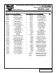
Universal Small Block Chevy Carbureted V2 Si-TRIM Part No. 4GP218-030SQ/038SQ PARTS LIST ® ENGINEERING, INC IMPORTANT: Part No. Before beginning installation, verify that all parts are included in the kit. Report any shortages or damaged parts immediately. Description 2E128-040 S/C CHEV UNIV CARB, GEN2 V2 2A032-333 S/C DRIVE PLY, 3.
Universal Small Block Chevy Carbureted V1 T-Trim Part No. 4GP218-030T/038T PARTS LIST ® ENGINEERING, INC IMPORTANT: Before beginning installation, verify that all parts are included in the kit. Report any shortages or damaged parts immediately. Part No. Description 2A138-040 S/C CHEV UNIV CARB, GEN2 V1 2A032-333 S/C DRIVE PLY, 3.
Universal Small Block Chevy Carbureted V7 YSI-Trim Part No. 4GP218-030YSI/038YSI PARTS LIST ® ENGINEERING, INC IMPORTANT: Part No. Before beginning installation, verify that all parts are included in the kit. Report any shortages or damaged parts immediately. Description 2A158-070 S/C CHEV UNIV CARB, GEN2 V7 2A032-333 S/C DRIVE PLY, 3.
Universal Small Block Chevy Carbureted V3 Si-Trim Entry Level Kit Part No. 4GP218-050L/058L PARTS LIST ® ENGINEERING, INC IMPORTANT: Before beginning installation, verify that all parts are included in the kit. Report any shortages or damaged parts immediately. Part No.
1. PREPARATION/REMOVAL A. B. C. D. 2. Disconnect the negative lead to the battery. Remove the fan and shroud to aid in installation. It may also be necessary to install a fan spacer at a later time. (V-Belt Equipped Applications) 1. Loosen all nuts and bolts that are used to tension the alternator and power steering pump V-belts. Remove the factory belts. 2. Remove the factory power steering pump from the engine. (Serpentine-Belt Equipped Applications) 1.
3. OIL DRAIN INSTALLATION (OIL-FED UNITS ONLY) A. To provide an oil drain for the supercharger, it is necessary to make a hole in the oil pan. Locate and mark the hole location. (See Fig. 3-a.) It is best to punch the hole rather than drill. NOTE: B. C. D. Remove any paint from around the hole area. Use a small center punch to perforate the pan and expand the hole, switch to a larger diameter punch and expand the hole further to approximately ø9/16".
4.1 MAIN BRACKET/SUPERCHARGER INSTALLATION (Serpentine) NOTE: A. B. C. Some applications (depending on intake manifold height) may require the reclocking of the supercharger volute. If reclocking is required for your application, loosen and remove the six 1/4-20 cap screws and retaining plates that hold the compressor housing (volute) to the gearcase. If the compressor housing does not rotate freely relative to the gearcase, DO NOT FORCE IT. SERIOUS SUPERCHARGER DAMAGE MAY OCCUR.
4.1 D. MAIN BRACKET/SUPERCHARGER INSTALLATION (Serpentine), cont’d Dual-Plate Applications Only: 1. Locate the supplied steel supercharger mounting plate. Attach the plate to the cast aluminum mounting bracket with the two supplied 3/8-16 x 1” screws in the locations shown in Fig 4.1-c. Do not tighten the screws at this time. They will be removed in a future step. Leave finger tight. 2. Place the supercharger into position on the steel supercharger mounting plate.
4.1 MAIN BRACKET/SUPERCHARGER INSTALLATION (Serpentine), cont’d 5. Locate the supplied idler hardware and idler shown in Figs. 4.1-e, 4.1-f, and 4.1-g. Apply a small amount of antiseize lube to the threads of the idler adjustment screw (3/8-16 threads). Attach the idler and hardware as shown. Do not tighten the hardware until the belt is fitted and installed in a future step. 4.1-e 4.1-f 4.1-g 5 P/N: 4GP020-015, v3.0, 2012-03-26 ©2012 Vortech Engineering, Inc. All Rights Reserved, Intl. Copr.
4.1 E. F. G. H. 4.2 A. MAIN BRACKET/SUPERCHARGER INSTALLATION (Serpentine), cont’d Mount the power steering pump (if equipped) to the back side of the cast bracket using the supplied 3/8-16 flat-head screws. Reinstall the power steering pulley. (See Figs. 4.2-b, 4.2-c.) Mount the alternator to the mounting plate with the supplied 8mm hardware. (See Fig. 4.1-h.) Oil-Fed Applications Only: Attach the oil drain hose to the 1/2" barbed fitting on the bottom of the supercharger.
4.2 MAIN BRACKET/SUPERCHARGER INSTALLATION (V-Belt), cont’d 2. 3. Mount the power steering pump to the back side of the cast bracket using the supplied 3/8-16 flat-head screws. Locate the power steering pump drive flange. Using the appropriate GM power steering pulley installer, install the drive flange as you would a normal power steering pulley. (See Fig. 4.2-b.) Using the six 1/4-20 x .75" screws and washers, attach the supplied power steering pulley. (Blue loc-tite on the threads is recommended.
E. Dual-Plate Applications Only: 1. Locate the supplied steel supercharger mounting plate. Attach the plate to the cast aluminum mounting bracket with the two supplied 3/8-16 x 1” screws in the locations shown in Fig 4.2-d. Do not tighten the screws at this time. They will be removed in a future step. Leave finger tight. 2. Place the supercharger into position on the steel supercharger mounting plate.
5. F. G. Locate the supplied idler hardware and idler shown in Figs. 4.2-f, 4.2-g, and 4.2-h. Apply a small amount of antiseize lube to the threads of the idler adjustment screw (3/8-16 threads). Attach the idler and hardware as shown. Do not tighten the hardware until the belt is fitted and installed in a future step. Oil-Fed Applications Only: Attach the oil drain hose to the 1/2" barbed fitting on the bottom of the supercharger. Secure the hose with the supplied hose clamp.
5. CRANK PULLEY AND SUPERCHARGER DRIVE PULLEY INSTALLATION NOTE: Two crank pulley spacers are provided in this system. 4GP017-031 (3.695" long) is to be used for serpentine drive systems. The 4GP017-041 (3.293" long) is to be used for V-belt applications. A. B. Locate the supercharger drive assembly (4GP116-041). Using the 7/16-20 x 2.75" screw and washer, loosely install the appropriate spacer for your application to the front of the factory crank pulley.
TENSIONER PLATE THREE M12 x 1.75" x 20mm SCREWS AND WASHERS TENSIONER PULLEY 7/16 -14 x 3" Fig. 5-c (10-Rib Application Shown) 11 P/N: 4GP020-015, v3.0, 2012-03-26 ©2012 Vortech Engineering, Inc. All Rights Reserved, Intl. Copr.
6.1 DISCHARGE DUCTING/CARBURETOR ENCLOSURE (NON-ENTRY LEVEL KITS) NOTE: 1. 2. 3. 4. A. B. C. OPTIONAL: Due to the many possible configurations of intake manifolds (with regard to carburetor flange height) a carburetor spacer may be required to obtain the necessary height for proper supercharger and discharge duct alignment. As an option, the carburetor enclosure cover may be turned around so that the inlet is facing the passenger side of the vehicle.
6.2 A. B. C. D. E. F. G. H. I. J. K. DISCHARGE DUCTING/CARBURETOR HAT (ENTRY LEVEL V3 KITS) Locate the 8M106-011 carb hat assembly. Place the carb hat housing bottom side up on a non-marring surface. Place the diffuser onto the receiver groove machined into the carb hat housing. (See Fig. 6.2-a) Place the carb hat base onto the housing, making sure the diffuser seats into the base's machined groove. Orient approximately as shown. (See Fig. 6.
7. FINAL REASSEMBLY AND CHECK WARNING: Do not attempt to operate the vehicle until all components are installed and all operations are completed including final check. A. B. C. D. E. F. G. H. I. J. K. L. M. Refit the fan and shroud (if equipped). Fuel pump boost reference hose connection: Connect a suitable boost reference hose to the mechanical fuel pump (or to the regulator if an electric pump and bypass-style fuel system is employed) to a positive pressure source upstream of the throttle valve.
(this page intentionally left blank) P/N: 4GP020-015 v3.0, 2012-03-26 ©2012 Vortech Engineering, Inc. All Rights Reserved, Intl. Copr.
® ENGINEERING, INC. 1650 Pacific Avenue, Channel Islands CA 93033-9901 • Phone: 805 247-0226 Fax: 805 247-0669 • www.vortechsuperchargers.com DP/N: 4GP020-015 - v3.