
Owner manual


P/N: 4GP020-015, v3.0, 2012-03-26
©2012 Vortech Engineering, Inc.
All Rights Reserved, Intl. Copr. Secured
12
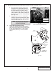
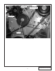
Fig. 6.1-a (Optional)
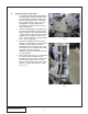
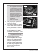
Fig. 6.1-b (Optional)
A. Install Vortech carburetor enclosure (if not
already completed) assembly #8M205-012
included in this kit. Instructions are included
in the enclosure assembly.
B. Locate the 4GP112-040 discharge assembly.
Using the supplied gasket and 5/16-18 x 3/4"
socket-head screws from the carburetor
enclosure assembly, secure the 3/5" alumi-
num flange to the carburetor enclosure lid.
C. Install the 3/5" x 2.75" 90° elbow (7S350-276)
between the supercharger discharge and the
3.5" aluminum flange previously installed.
Trim the ends if necessary for best fit. Secure
using a #44 and #56 hose clamp.
NOTE: OPTIONAL: Due to the many possible configu-
rations of intake manifolds (with regard to carbu-
retor flange height) a carburetor spacer may be
required to obtain the necessary height for prop-
er supercharger and discharge duct alignment.
As an option, the carburetor enclosure cover
may be turned around so that the inlet is facing
the passenger side of the vehicle. This may be
desirable on some vehicle applications with tall
intake manifolds or for vehicles with other clear-
ance issues. (See Figs. 6.1-a, 6.1-b for more
detail.)
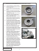
1. This optional discharge arrangement requires
the supercharger to be sent into Vortech for a
volute exchange to a straight discharge unit (a
curved volute is originally supplied on the super-
charger).
2. An extended discharge elbow must be pur-
chased from Vortech (#4GA012-021).
3. Also a discharge elbow must be purchased from
Vortech (#8M012-012).
4. Routing of the fuel line inlet to the rear of the
enclosure must also be performed.
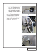
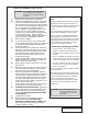
NOTE: The 7S350-276 is made to be trimmed in
order to fit, allowing for various intake mani-
fold heights.
4GA012-021
8M012-012
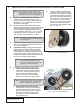
D. Compressor Bypass Valve Placement:
Vortech suggests attaching the compressor
bypass valve (bypass valve and mounting
flange are not included) onto the supercharg-
er discharge tube. After all of the major kit
components have been installed, mock-up
the bypass valve and flange so that proper
clearance to vehicle hood and surrounding
components is confirmed. Actual valve loca-
tion will vary depending on the specific appli-
cation. After the bypass flange and valve are
permanently mounted, connect the bypass
valve vacuum port to a proper vacuum
source on the engine.