TimeLord-Net Master Clock Operations Manual Revision 2.0 Vortex Communications Ltd 75 The Grove, Ealing LONDON W5 5LL, UK Tel: +44-(0)20-8579 2743 Fax: +44-(0)20-8840 0018 E-Mail: info@vtx.co.
TimeLord Master Clocks Operating and Installation Instructions © 1999-2006 All rights reserved. For Customers in Europe In the interests of improving design, operational function, and/ or reliability, we reserves the right to make changes to the products described in this document without notice.
TimeLord Master Clocks Operating and Installation Instructions Contents 1 2 3 4 Introduction Features 1-1 Package Contents 1-1 Quick Start and TimeLord Programming Quick Start 1-4 2-1 Quick Start 5-8 2-2 Frequently Asked Questions 2-3 TimeLord Programming 2-4 Programming menus 2-4 Setting the time and date 2-6 Leap second insertion 2-7 Status display 2-7 System set-up 2-8 Installation Location Setup City / Location Table 5 Synchronisation Setup GPS Synchronisation 5-1 MSF and D
TimeLord Master Clocks Operating and Installation Instructions 1 - Introduction TimeLord series Master Clocks provides an ideal time synchronisation solution for complete systems of equipment, including computer networks, CCTV security, voice recording, industrial process control and CCC applications. Available as standard with MSF, DCF and GPS input synchronisation options, optionally the TimeLord can be supplied to synchronise from an NTP time source or from IRIG-B time code.
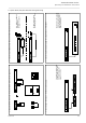
Issue 2.0 3 - Connecting V-400A and V-470/474A slave displays For details on synchronising V-400A series clocks and time-zone displays see pages 6-1 and 6-2. 1 - Unpack the TimeLord and check contents matches list on page 1-1. See sections 7 and appendix A of manual and application notes on TimeLord CD for further information. 4 - Connecting third-party equipment using RS232 or RS422/485 For radio synchronisation (V-484)see pages 5-1 & 5-3.
2-2 7 - Connecting Impulse slave clocks. For further information on connecting a TimeLord with -02 interface to Impulse slave clocks see chapter 12. For further information on connecting a TimeLord with IRIG-OUT option to equipment using IRIG timecode see page 10-1. For further information on connecting a TimeLord with EBU-OUT to other equipment using EBU timecode see pages 11-1 and 11-2. 5 - Connecting third-party equipment using EBU and IRIG. 8 - Apply power and set time on TimeLord.
TimeLord Master Clocks Operating and Installation Instructions Frequently Asked Questions Will the V-488C / V-488B GPS receiver system work indoors? The V-484.06 MSF and V-484.07 DCF radio time code receivers are suitable for indoor use only. Both the V-488C and the V-488B GPS receiver systems are designed for external mounting. We would recommend positioning the post-mounting V-488C GPS system on the roof of the building with a clear view of at least 75% of the sky.
TimeLord Master Clocks Operating and Installation Instructions TimeLord Progamming S2 Serial Output Setting mode (.S2 & .S4 versions The TimeLord Master Clock has a user friendly interface based on the use of four buttons. The buttons are located to the right hand side of the display . and are labelled and only) S3 Serial Output Setting mode (.S4 versions only) S4 Serial Output Setting mode (.
TimeLord Master Clocks Operating and Installation Instructions Programming menus cont. Function ‘Zone Setting Mode’. ‘^’ to select, ‘+’ or ‘-’ to change. ‘Serial 2 Setting Mode’ will only appear on .S2 & .S4 versions. ‘Serial 3 Setting Mode’ & ‘Serial 4 Setting Mode’ will only appear on .S4 versions. ‘IRIG Setting Mode’ will appear on all versions, but only be usable on -IRIG-OUT versions. ‘EBU Setting Mode’ will only appear on EBU-OUT versions.
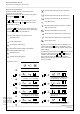
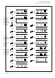
TimeLord Master Clocks Operating and Installation Instructions Setting the Time A detailed diagram with full instructions on manually setting the time and date is shown below. Normal time display Function ‘Time Setting Mode’. Press ‘^’ to select. Time setting mode selected, with seconds flashing. ‘+’ increments the seconds count, ‘-’ holds the seconds count at the current value. Time setting mode selected, with minutes flashing. ‘+’ and ‘-’ change the minutes value.
TimeLord Master Clocks Operating and Installation Instructions Leap Second Insertion The TimeLord can be programmed to allow for leap second insertion (one second is sometimes added at the end of March, June, September or December), to compensate for the deceleration of the Earth’s rotational time with respect to the the Atomic clock (UTC). This function is enabled by programming the ‘LS’ setting to yes (as shown on page 2-6).
TimeLord Master Clocks Operating and Installation Instructions System Set-up The system set-up menu contains general set-up options for the TimeLord Master Clock. The table below details the available options. Normal time display System set-up menu Code Function Options Bri Display Brightness 1 - 4. (1 = Dimmest) o ut w482 output type w482, DCF, MSF, -DCF, -MSF, L48, S48, HBG, -HBG VA TimeLord version VB network software version EnG factory use only Function ‘Time Setting Mode’.
TimeLord Master Clocks Operating and Installation Instructions 3 - Installation TimeLord-Lite/T Desktop version TimeLord-Lite - no expansion capability TimeLord-Net and TimeLord-Net-Client Warning - dangerous voltages - the TimeLord master clock must be disconnected from the mains supply prior to removing the top cover. Power Supply Connection The TimeLord family of master clocks are fitted with universal power supplies suitable for 110v - 240v ac operation.
TimeLord Master Clocks Operating and Installation Instructions 4 - Location Setup The TimeLord Master Clock provides advanced time zone functionality. Regardless of time synchronisation source, the TimeLord can be used to provide time and date information referenced to UTC, user ‘local’ time or other custom time zone. Incorporating ‘Set Once’ technology, the TimeLord will automatically calculate future seasonal time changes for all 64 of the preset time location code settings.
Issue 2.0 Vladivostok Magadan, Solomon Is., New Caledonia Auckland, Wellington Fiji, Kamchatka, Marshall Is.
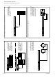
TimeLord Master Clocks Operating and Installation Instructions GPS Synchronisation 5 - Synchronisation Setup - + A B A GPS Receiver B no nc C GPS connection Relay w482 10 way terminal block + A B -ve Power for V-488B/C GPS +ve Power for V-488B/C GPS Signal A from V-488B/C GPS Signal B from V-488B/C GPS EMC grounding point Note: A Screened cable should be used to connect the V-488C / V-488B GPS receiver to the TimeLord .
TimeLord Master Clocks Operating and Installation Instructions Both the V-488C and the V-488B GPS Receiver systems are supplied with 25 metres of 4 core cable. Cable distance can be extended up to a maximum distance of 200 metres using the cable specifications detailed in appendix A. V-488C GPS Receiver Should be mounted with a view of at least 75% of the sky. 20mm dia. post (not supplied) V-488B Antenna Should be mounted with a view of at least 75% of the sky.
TimeLord Master Clocks Operating and Installation Instructions MSF and DCF synchronisation MSF and DCF are the two most widely used radio time code signals. The DCF signal is derived from the atomic clocks at the Physics Institute of Brunswick and transmitted at a frequency of 77.5KHz from Manflingen, near Frankfurt in Germany. The MSF signal is referenced to the Caesium Beam Oscillators at the National Physical Laboratory and transmitted on a frequency of 60KHz from Rugby in the United Kingdom.
TimeLord Master Clocks Operating and Installation Instructions 6 - w482 Time Zone Setup TimeLord w482 Code Output 10 way terminal block A B w482 Code + w482 Code EMC grounding point Normal time display Note: Polarity of connection is not critical. If a screened cable is used for system interconnection, the screen should only be connected to the EMC grounding point on the TimeLord.
TimeLord Master Clocks Operating and Installation Instructions w482 time code system interconnection RS232/RS485 S3 RS232/RS485 S4 Link Data MAC Address 10Base-T xx xx xx xx xx xx Net Update RS232/RS485 S2 - + A GPS Receiver B A B w482 no nc Relay C RS232/RS485 S1 IRIG-B Issue 2.
TimeLord Master Clocks Operating and Installation Instructions 7 - RS232 & RS422/485 Serial Output TimeLord RS232 & RS485/422 Interface DB9-F Connector RS232 RS232/RS485 S1 1 1PPS 2 Transmitted Data (TXD) 3 Received Data (RXD) 5 Signal Ground (GND) RS485/422 8 ‘A’ - non-inverting 9 ‘B’ - inverting Note: Data Formats The serial messages numbered from 01 to 09 are user programmable.
TimeLord Master Clocks Operating and Installation Instructions Serial Messages Code Message Format Repetition Transmission Format Notes 01 Std-serial Format 1 User Programmable User Programmable 02 Std-serial Format without status User Programmable User Programmable 03 Std-serial Format 2 User Programmable User Programmable 04 Std-serial Format 2 with day of week User Programmable User Programmable 05 Racal ICR64 User Programmable User Programmable 06 Schauer User Programmable U
TimeLord Master Clocks Operating and Installation Instructions Serial Messages (cont.) Code Message Format Repetition Transmission Format Notes (Please refer to specified application note on CD-ROM) 32 Philips LTC2600 Multiplexer US Burle TC8286 & TC8288 Multiplexers. Allegiant LTC8300 Series, LTC8511C, LTC8610/00, TC8719A, LTC 8810/00, LTC8910/00 with CPU rev 7.
TimeLord Master Clocks Operating and Installation Instructions Serial Messages (cont.
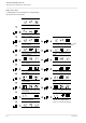
TimeLord Master Clocks Operating and Installation Instructions Serial Setting Mode Normal time display Function ‘Time Setting Mode’. ‘^’ to select, ‘+’ or ‘-’ to change. Function ‘Serial Mode’. Press ‘^’ to select. Serial Mode with serial type flashing. Use ‘+’ and ‘-’ to select. ‘+’ and ‘-’ change the selected serial output message. Baud rate selected, with current setting flashing. ‘+’ and ‘-’ change the baud rate. ‘PRESET’ indicates the setting cannot be changed.
TimeLord Master Clocks Operating and Installation Instructions 8 - Relay Setup TimeLord Relay Connections 10 way terminal block no N.O. Contact nc N.C. Contact C Common Note: The relay is configured so that contacts no-C are normally open and contacts nc-C are normally closed. For example, if the relay is set to close every hour for 100ms, contacts no-C will close for 100ms on the hour, while contacts nc-C will open for 100mS.
TimeLord Master Clocks Operating and Installation Instructions 9 - Network Configuration (TimeLord-Net versions only) Link Data 10Base-T Net Update Quick Setup Install the TimeLord-Net as detailed in section 3 of this manual. Attention: If you are unsure of the following network settings please contact your network administrator. Incorrect settings can adversely affect the performance of your network.
TimeLord Master Clocks Operating and Installation Instructions Class A Class B Class C 0 7 bits 24 bits Network Host 1 0 1 14 bits 16 bits Network Host 1 0 For the class B subnet example used above the subnet mask would be as follows: Class B 21 bits 8 bits Network Host 28 bits Class D 1 1 1 0 Multicast group 27 bits Class E 1 1 1 1 0 Experimental 24 bits 8 bits 1111 1111 1111 1111 1111 1111 0000 0000 The following table details a few typical subnet masks and the network
TimeLord Master Clocks Operating and Installation Instructions Supported Protocols Time Protocol (RFC868) RFC868 defines the original TIME protocol, which provides siteindependent, machine-readable date and time in response to a request from a client PC. When a request is received the TimeLord-Net responds with a 32-bit time value corresponding to the number of seconds since midnight of January 1st 1900. This representation of time will serve until the year 2036.
TimeLord Master Clocks Operating and Installation Instructions Network setting menu Normal time display Function ‘Time Setting Mode’. Press ‘+’ three times to move to Network setting mode. Function ‘Network Setting Mode’. Press ‘^’ to select. 9-4 Network Setting Mode, with IP address 1st byte flashing. Use ‘+’ and ‘-’ to change setting. Network Setting Mode, with IP address 2nd byte flashing. Use ‘+’ and ‘-’ to change setting. Network Setting Mode, with IP address 3rd byte flashing.
TimeLord Master Clocks Operating and Installation Instructions Network Setting Mode, with Subnet mask 4th byte flashing. Use ‘+’ and ‘-’ to change setting. Network Setting Mode, with Gateway address 1st byte flashing. Use ‘+’ and ‘-’ to change setting. Network Setting Mode, with Gateway address 2nd byte flashing. Use ‘+’ and ‘-’ to change setting. Network Setting Mode, with Gateway address 3rd byte flashing. Use ‘+’ and ‘-’ to change setting.
TimeLord Master Clocks Operating and Installation Instructions 10 - IRIG Output (IRIG-OUT Option) Optional IRIG Interface BNC Connector 1KHz AM modulated balanced signal. Normal time display If your TimeLord is fitted with NTP, S2 or S4 options, you may need to press the ‘+’ switch more than 7 times.
TimeLord Master Clocks Operating and Installation Instructions 11 - EBU Output (EBU-OUT option) Ω TimeLord-Net EBU Timecode Interface 6 way terminal block Low Z Low impedance signal 600Ω Balanced 600Ω signal Normal time display If your TimeLord is fitted wtih NTP, S2 or S4 serial options, you may need to press the ‘+’ switch more than 8 times. Function ‘Time Setting Mode’. Press ‘+’ eight to times to move to EBU setting mode.
TimeLord Master Clocks Operating and Installation Instructions EBU timecode output formats Data Bit Format A - data bit content Format B - data bit content Format C - data bit content 0 1 2 3 4 5 6 7 8 9 10 11 12 13 14 15 16 17 18 19 20 21 22 23 24 25 26 27 28 29 30 31 32 33 34 35 36 37 38 39 40 41 42 43 44 45 46 47 48 49 50 51 52 53 54 55 56 57 58 59 60 61 62 63 64 65 66 67 68 69 70 71 72 73 74 75 76 77 78 79 1 2 4 8 0 0 0 0 10 20 0 0 0 0 0 0 1 2 4 8 0 0 0 0 10 20 40 0 0 0 0 0 1 2 4 8 0 0 0 0 10 20 4
TimeLord Master Clocks Operating and Installation Instructions 12 - Impulse Output (V-02 Option) V-02 .IMP Dual Impulse Output 6 way terminal block Impulse 1 Impulse 2 Impulse Channel 1 Impulse Channel 2 Operation Commissioning Please perform the following four procedures to commission your impulse clock system. Setup Part A - Initial Setup Procedure Before commencing this procedure, please ensure that all of the clocks are displaying the same time.
TimeLord Master Clocks Operating and Installation Instructions Impulse channel setup procedure This procedure enables the master clock to know what time the slave clocks are displaying and thus calculate the required number of catch-up pulses. It also ensures that the correct type of impulses are output. This procedure must be performed for both channels (if used) on initial commissioning.
TimeLord Master Clocks Operating and Installation Instructions This procedure will start the impulses running and should only be performed once the impulse channel setup procedure has been completed. Once the channel has been started, the master clock will calculate whether it will be quicker to output catch-up impulses or wait for the current time to reach the impulse time (as previously programmed). This procedure must be performed for both channels (if used).
TimeLord Master Clocks Operating and Installation Instructions Impulse system interconnection Link Data MAC Address 10Base-T xx xx xx xx xx xx Net Update RS232/RS485 S2 - + A GPS Receiver B A B w482 no nc Relay C RS232/RS485 S1 IRIG-B Issue 2.
TimeLord Master Clocks Operating and Installation Instructions Appendix A - Cable Specifications TimeLord-> V-488B/C GPS interconnection The V-488B and V-488C GPS Receiver systems are supplied with 25 metres of four core 7/0.2 (0.22mm2) screened cable. The cable screen should be grounded at the TimeLord end by means of the EMC rear grounding terminal and on the V-488B GPS receiver using the screw fitting provided.
TimeLord Master Clocks Operating and Installation Instructions Appendix B - Case dimensions TimeLord Rackmount Case - dimensions TimeLord-T Desktop Case - dimensions B-1 Issue 2.
TimeLord Master Clocks Operating and Installation Instructions Appendix C - Supported devices Listed below are some CCTV and other devices with known time synchronisation support from the TimeLord Master Clock. Please refer to the relevant chapters of this manual (and if applicable, the application notes located on the CDROM supplied) for further information on synchronisation procedures.
TimeLord Master Clocks Operating and Installation Instructions Appendix C - Supported devices - cont.
TimeLord Master Clocks Operating and Installation Instructions Appendix C - Supported devices - cont.
TimeLord Master Clocks Operating and Installation Instructions Appendix D - NTP Synchronisation option (TimeLord-Net-Client versions only) Link Data 10Base-T Net Update MAC Address Quick Setup Install the TimeLord-Net-Client as detailed in section 3 of this manual. Attention: If you are unsure of the following network settings please contact your network administrator. Incorrect settings can adversely affect the performance of your network.
TimeLord Master Clocks Operating and Installation Instructions Synchronisation Status Display When in normal time display mode the plus and minus buttons can be used to cycle through the date, synchronisation and temperature status displays, as detailed on page 2-5. However, when NTP is selected as the synchronisation source, the synchronisation status display operates as detailed below NTP Synchronisation status - please refer to the table below for further information.
TimeLord Master Clocks Operating and Installation Instructions When the TimeLord master clock is programmed to synchronise from an NTP time source, the network setting menu will be replaced by the following netclient setup menu. Normal time display Function ‘Time Setting Mode’. Press ‘+’ three times to move to Netclient setting mode. Function ‘Netclient Setting Mode’. Press ‘^’ to select. Netclient Setting Mode, with IP address 1st byte flashing. Use ‘+’ and ‘-’ to change setting.
TimeLord Master Clocks Operating and Installation Instructions Netclient Setting Mode, with NTP Server IP Address 3rd byte flashing. Use ‘+’ and ‘-’ to change setting. Netclient Setting Mode, with NTP Server IP Address 4th byte flashing. Use ‘+’ and ‘-’ to change setting. Netclient Setting Mode, with Network update flashing. This mode cannot be exited if set to ‘y’. Use ‘+’ and ‘-’ to change setting.
Vortex Communications Ltd 75 The Grove, Ealing, London. W5 5LL Email: info@vtx.co.uk WWW: http://www.vtx.co.