Pellet Vent INSTALLATION INSTRUCTIONS A MAJOR CAUSE OF CHIMNEY RELATED FIRES IS FAILURE TO MAINTAIN REQUIRED CLEARANCES (AIR SPACES) TO COMBUSTIBLE MATERIALS. IT IS OF THE UTMOST IMPORTANCE THAT THIS PELLET VENT BE INSTALLED ONLY IN ACCORDANCE WITH THESE INSTRUCTIONS. This Pellet Vent Pipe meets the requirements of the NFPA 211, CSA B365, UL 641, CAN/ULC S609 and ULC/ORD C441 Standards. Read through these instructions before beginning your installation.
TABLE OF CONTENTS General Product Information .......................................................................3 Codes & Permits ................................................................................................................. 3 Product Applications ............................................................................................................ 3 General Specifications .................................................................................3 Codes & Clearances .
GENERAL PRODUCT INFORMATION The quality and workmanship of SBI Venting Division Pellet Vent Pipe is reflected in the recognition by an accredited laboratory has given these products. The rigorous UL and ULC testing requirements are your assurance of consistent quality, in materials and manufacturing standards, used for this chimney system. In addition, the industry leading Warranty on SBI Venting Division Pellet Vent Pipe is a further indication of our confidence in the quality of these products.
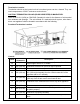
Termination Location Termination should not be located so that hot exhaust gases can be a hazard. They can reach temperatures of 500 ºF and cause serious burns. CAUTION: TERMINATION COLLAR (SPARK ARRESTER) IS MANDATORY. Refer to NFPA 211 (USA) or CSA B365 (Canada) for rules for the distance of exit terminal from windows and openings. The exit terminal of a mechanical draft system, other than a direct vent appliance shall be located in accordance with the following.
United States: • • • • • • • Not Less than 36" (91 cm) above any forced air inlet located within 10 feet (305 cm); Not Less than 48" (122 cm) below and horizontally from, or one foot (30 cm) above, any door, window or gravity air inlet into any building; Not Less than 24" (61 cm) from an adjacent building and not less than 84" (213 cm) above grade when located adjacent to a public walkway. Cannot be located less than 12" (300 mm) above grade.
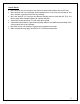
INSTALLATION PREPARATION EQUIPMENT, TOOLS AND HARDWARE Tools: Plumb Bob Reciprocating Saw Keyhole Saw Metal Snips Hammer Drill Level Tape Measure Caulk Gun Screw Drivers Equipment: Ladder Safety Glasses Protective Gloves Hardware: Framing Nails Roofing Nails High Temperature Silicone Sealant SBI Venting Division Pellet Vent Components (Part No.
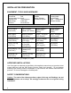
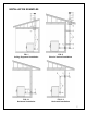
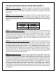
INSTALLATION EXAMPLES FIG. 1 Ceiling Supported Installation FIG. 2 Exterior Vertical Installation FIG. 3.1 Horizontal Installation FIG. 3.
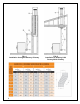
FIG. 4 Installation through a Masonry Chimney 8 FIG.
CEILING SUPPORTED INSTALLATION (SEE FIGURE 1) Step 1- Position appliance: Locate the appliance in accordance with the appliance manufacturer’s instructions and clearance/ventilation specifications. Pay particular attention to the outlet flue collar of the appliance and endeavor to position it between the rafters and joists above. Step 2- Frame ceiling opening: Use a plumb bob from the ceiling to the center of the appliance outlet flue collar and mark this point on the ceiling above.
Step 6- Completing the Top Termination: Fasten the Roof Support on each side with four 8-penny nails or four #8 x 1-1/2” wood screws. Use the pivot adjustment on the Roof Support to ensure the pipe is centered through the roof cutout and a minimum of a 1” clearance is maintained around the pipe. Slide the Roof Flashing (E) over the chimney and place the Flashing under the upper shingles and on top of the lower shingles.
HORIZONTAL INSTALLATION (SEE FIGURES 3.1 & 3.2) Step 1- Position appliance: Locate the appliance in accordance with the appliance manufacturer’s instructions and clearance specifications. Pay particular attention to the outlet flue collar of the appliance and endeavor to position it between the wall studs.
INSTALLATION THROUGH A MASONRY CHIMNEY (SEE FIGURE 4) Step 1- Position appliance: Locate the appliance in accordance with the appliance manufacturer’s instructions and clearance specifications. Mark the center of the hole where the pipe is to penetrate the masonry chimney. Step 2- Prepare the wall opening: If the masonry chimney has an existing 6” terra cotta thimble, please skip to step #3.
MAINTENANCE INSTRUCTIONS This pellet vent system must be installed and serviced by a qualified chimney or venting professional. The criteria for the inspection and maintenance must be in conformance with local or state building codes, whichever has jurisdiction. It is recommended you use an inspection form and make notes that you can review with the homeowner.
SBI VENTING DIVISION LIMITED LIFETIME WARRANTY - Pellet Vent Pipe - The warranty: The manufacturer’s warranty applies only to the original purchaser and is not transferable. Subject to the conditions and exclusions set forth below, the manufacturer warrants that its products will be free from manufacturing if properly installed. This warranty only covers replacement of defective pellet vent pipe components in a residential installation.
The paint used on the black SBI Venting Division pellet vent pipe is 100% covered by a 1 year warranty on peeling. This warranty covers the transportation costs for replacement parts. These will be delivered FOB Saint-Augustin-de-Desmaures (Quebec) to the your nearest Olympia Chimney of Canada retailer. The parts covered by lifetime warranty are subject to a limit of one replacement on the useful life of the product. Silicone gasket – Part replacement covered at 100% for 10 years from the date of purchase.