RADIO CONTROL MODEL / RC FLUGMODELL INSTRUCTION MANUAL SPECIFICATIONS Wingspan.......57.5 in. / 146cm Length...............50 in. / 127cm Engine................46 2T / .70 4T or Electric equivalent. Radio..................4 ~ 6 channel Almost ready to fly WARNING! This radio control model is not a toy. If modified or flow carelessly it could go out of control and cause serious bodily injury or property damage. Before flying your airplane, ensure the air field is spacious enough.
REQUIRED FOR OPERATION (Purchase separately) 10.5x6 for .40 - 2 cycle engine 11x6 for .46 - 2 cycle engine 12x6 for .60 - 4 cycle engine 12x7 for .70 - 4 cycle engine 13x8 for G-46 HP Motor. Extension for aileron servo, retract servo. Motor Control Retract landing gear VQAR03 16023 Minimum 5 channel radio for airplane with 5 servos .Motor control x1 .Elevator x1 .Rudder x1 .Aileron x2 .60 ~.70 - 4 cycle .46 ~ .50 - 2 cycle Retract servo x1 G-46 HP Motor or equivalent.
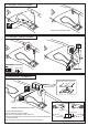
1- Joining the wing Cut the opening hole (½”x1/2”) throughout the balsa wood for the aileron extension cord exit. WING - TOP VIEW WING ROOT Using the thread (pre-installed at factory) to slide the aileron extension cord into the wing half. Thread (pre-installed at factory) Secure one end of the aileron extension cord with adhesive tape Do the same way with other wing half.
3- Retract servo tray CA CENTER WING SECTION Retract servo mount B CA Retract servo tray 1/8(3mm plywood) C Retract servo mount A B Secure one end of the aileron extension cord with adhesive tape C BOTTOM CA A TOP VIEW CA Retract servo tray installation Cut away only the covering 4- Servo Installation TOP VIEW RETRACT SERVO INSTALLATION Note: The head of servo should be positioned toward the rear of the wing. Retract landing gear servo X CENTER WING SECTION BOTTOM 1/16” 1.
Link the servo and retract gear arm with push rod. Be sure to adjust the stroke so that the landing gear locks in both up and down position. 6- Retract landing gear Installation Retract servo Retract gear Retract gear RETRACTED EXTENDED WING TOP-VIEW With the retract and retract servo in the retracted position, mark the position where each of the pushrod will attach to the servo arm, a small piece of masking tape works well for this. Cut off the excess length each rod.
9- Fixed gear / Starres Fahrwerk CA ABS Wheel well cover Bottom view /Ansicht von unten 10- Fixed gear / Starres Fahrwerk 2x6mm screw ..........4 CA 4mm collar ...2 ....2 11- Wing bolt flat / Verstarkung Wing bolt flat 1/8”(3mm)plywood Wing bolt flat CA Cut away only the covering Bottom view /Ansicht von unten Using the wing bolt flat as a template, trace around the outside edge of the wing bolt flat and then remove it. Using a sharp hobby knife, cut away the covering inside the lines.
12- Wing bolt flat / Verstarkung Drill the holes throughout the wing bolt plat , from the top to the bottom of the wing. WRONG RIGHT TOP 17/64” 6.5mm WING BOTTOM -Switch on the radio (trims centered) then mount the ailerons servo horn in neutral position.
15- Air Scoop/wing cover 6x40mm nylon bolt 15/32” 12mm Plastic air scoop .........2 CA Wing cover CA Wing bolt plat 1/8”(3mm) ply Cut away the covering inside the line before install the air scoop and wing cover BOTTOM-VIEW 1-Using the ABS air scoop as a template, trace around the outside edge of the ABS air-scoop,and then remove it. 2-Using a sharp hobby knife, cut away the covering inside the lines. Not to cut into the wood. 3-Apply the ABS air scoop in place and secure with CA glue.
Securely glue together. If coming off during flight, you lose control of your air plane. 18- Horizontal stabilizer Vergewissern Sie sich, sauber geklebt zu haben. Andernfalls konnen Probleme mit der Flugeigenschaft auftreten! Cut away only the covering both the right and left side B’ B Cut away only the covering both the top and bottom side* A = A’ B = B’ Both the top and bottom side A B 1-Trial fit the horizontal stabilizer in place . Check the alignment of the horizontal stabilizer.
20- Elevator installation Vergewissern Sie sich, sauber geklebt zu haben. Andernfalls konnen Probleme mit der Flugeigenschaft auftreten! Securely glue together. If coming off during flight, you lose control of your air plane. CA 3/8 in. (9.5mm) push the elevator and its hinges into the hinge slots in the trailing edge of the horizontal stabilizer. There should be a minimal hinge gap. When satisfied with the and alignment, hinge the elevator to the horizontal stabilizer using thin CA glue.
22- Engine mount - engine 5/32x1” 4x25mm screw 1/8x5-1/64” 3x20mm screw Blind-nut 1/8”(3mm) nut ...4 ! Align the mark on both mounts with the mark on the fuselage A A .................4 ...4 .................4 B A B’ FRONT-VIEW B=B’ 13/64” 5mm - Using a pencil or felt tipped pen, mark the fire wall where the four holes are to be drilled - Remove the engine mount and drill a 13/64”(5mm) hole through the fire-wall at each of the four marks marked.
1 23- Fuel tank 2 To muffler Filler tube Rubber stopper 3x25mm screw To engine X 3x35 mm screw 4mm After confirming the direction . Insert this assembly, clunk end first, into the fuel tank and tighten and screw the fuel tank cap on firmly.
26- Linkages Throttle push rod Elevator push rod BOTTOM VIEW Thrott. servo Elev. servo Rudder servo Elevator push rod Rudder push rod Tail wheel push rod Elevator pushrod 3mm set Screw 3mm set Screw throttle pushrod D=.050”(1.2mm) 2 mm 2 mm Connector X ................2 2mm ....................3 THROTTLE SERVO 27- Cowling installation Adhesive tape X ELEVATOR / RUDDER SERVO 1/16” 1~2mm 3/32x25/64” self tapping screw 2.5x10mm .................
28- Decor Note: Cut out the stickers and apply them in the proper area. Do not peel the backing paper off all at once. Peel off one corner of the backing and cut off with scissors. Arrange sticker on model and when satisfied adhere the corner without backing. Carefully peel back the rest of the backing while at the same time adhering the rest of the sticker.
30 Control Surface 15/64”(6mm) 15/64”(6mm) AILERON STROKE 1-23/64”(35 mm) RUDDER STROKE 1-23/64”(35 mm) 13/32”(10mm) ELEVATOR STROKE 13/32”(10mm) Adjust the travel of the control surfaces to achieve the values stated in the diagrams. These value will be suitable for average flight requirements. Adjust the values to suit your particular needs.