
User Manual


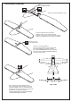
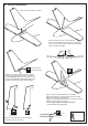


Table Of Contents

Firewall
C’
C
C=C’
! Engine thrust on balk head
is already adjust at factory
Using a aluminum motor mounting plate
as a template, mark the plywood motor mounting
plate where the four holes are to be drilled .
6mm
SIDE-VIEW
1-Attach the board or transparent plastic on the side of the fuselage with the adhesive tape as show.
2-Using a pencil or felt tipped pen trace around the engine head where it meet the cowl. Cut the opening the board or transparent
plastic for the engine head as marked before.
3-Remove the engine and insert the cowl on to the fuselage so the distance from the fire wall to the front of the cowl from124 to 130mm.
Trace around inside the hole on the board or transparent plastic with a pencil.
4-Remove the cowl from the fuselage and carefully cut the opening for the engine head as marked above. Do the same way with
the hole for needle-valve.
5-Again. Insert the cowl on to the fuselage and secure it in place with five 2.5x10mm self tapping screws.
13-Electric Motor
14-Cowling
Board or transparent plastic
Adhesive
tape
Cut the opening
2.5x10mm screw
...........3
Attach the four 6x100mm bolts, washers
and nuts to the fire-wall as shown.
3mm
3mm
Mark here
Remove the motor and drill a 3mm (1/8”) hole at
each of the four marks marked.
Apply the plywood motor mounting
onto the fire-wall. Align the marks
on the motor mounting with the marks
on the fire-wall. Mark the fire-wall
where the four holes are to be drilled.
Remove the motor mounting and
drill a 5mm hole at each of the
four marks marked.
Attach the motor to the motor mounting
and secure it in place using the four
3x20mm bolts and nuts.
MOTOR
124 - 130mm
B’
B
B=B’
TOP-VIEW
MOTOR
Plywood motor mounting
Firewall
6x100mm bolt.....4
6mm nut..........12
6mm washer...16
Mark here