
Installation guide


Installation guide 9 (of 14)
Liquid connections
□ Follow the instructions in the supplied LC connection kit installa-
tion guide for installation of all liquid connections. Connect the
tubing as it is shown in the drawing delivered with the connection
kit (180.7161A).
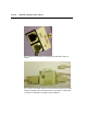
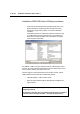
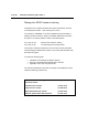
Fig. 6. As an example the front side of the schematic installation drawing of
all LC connections of the ROXY EC system is shown. Every kit is delivered
with a similar schematic installation drawing. This drawing is the most im-
portant guideline for the installation of all tubing assemblies of the LC con-
nection kit. Detailed instructions can be found in the supplied LC connec-
tion kit installation guide.
Note that the contents of LC connection kits differ depending on the
system purchased. Some kits contain tailor-made tubing assemblies
for all connections. Other kits consist of a set of all necessary hard-
ware (nuts, ferrules, finger tights and rolls of tubing) and instructions
to make all LC connections yourself.
□ Follow the ReactorCell user manual (210.7014) for installation of
the ReactorCell in the system.