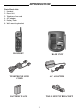
INTRODUCTION Parts Check List: 1. Handset 2. Base Unit 3. Telephone line cord 4. AC adapter 5. Battery Pack 6.
IMPORTANT SAFETY INSTRUCTIONS When using your telephone equipment, basic safety precautions should always be followed to reduce the risk of fire, electric shock and injury to persons, including the following: 1. Read and understand all instructions. 2. Follow all warnings and instructions marked on the product. 3. Unplug this product from the wall outlet before cleaning. Do not use liquid cleaners or aerosol cleaners. Use a damp cloth for cleaning. 4.
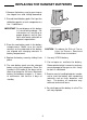
REPLACING THE HANDSET BATTERIES 1. Remove the battery case by pressing on the ridged lines and sliding downward. 2. Discard the old battery pack. Don't put the old battery pack in a trash compactor or a fire - it could burst. IMPORTANT: Do not dispose of this battery in household garbage. For information on recycling or proper disposal, consult your local solid waste collection or disposal organization. 3. Place the new battery pack in the battery compar tment.
SPARE BATTERY CHARGER SPARE BATTERY CHARGER Your VT 9121 ADLc is equipped with a spare battery charger built-in to the base unit. The spare battery charger allows you to always have a charged battery available, should your handset battery discharge during normal use. Contact your local VTech dealer, or call VTech Customer spare battery pack. Service to purchase a To install the Spare Battery Pack: 1. Open the base unit battery compartment. 2. Place the spare battery pack in the batter y compar tment.
GETTING STARTED PU LSE TO N E AC ELECTRICAL OUTLET PULSE TELEPHONE WALL JACK TONE Setting Up Your VT 9121 ADLc 1. Choose an area near an electrical outlet and a telephone wall jack. 2. Plug the AC power adapter into an electrical outlet and the DC connector to the back of the base unit. CAUTION:Use only the AC adapter shipped with your VT 9121 ADLc. This is a Class 2 AC adapter, specifically designed for use with the VT 9121.
WALL MOUNTING en od wotud s wa llb oa 1.Choose a spot near an electrical outlet and a telephone jack.Your phone requires a modular telephone jack and a standard electrical outlet (120V AC). The power cord is six feet long; make sure there is an electrical outlet within reach of the base. The outlet should not be controlled by a wall switch. If the switch is ever turned off, the phone will not operate. rd 4.Connect the telephone cord. The telephone line cord has a snap-in plug at each end.
HANDSET FEATURES IN USE/LOW BATT LED * The IN USE/LOW BATT LED lights when the phone line is being used by the handset. * It flashes in cadence with an incoming ring. * It flashes quickly during PGM mode. * It flashes slowly when a low battery is detected. PHONE KEY/ FLASH KEY * Press the PHONE key to make a call. * If you are currently on a call, pressing PHONE flashes the line. This would be used with a feature like call waiting to answer your second call.
BASE UNIT FEATURES CHARGING LED * The CHARGING LED illuminates steadily when the handset is in the base cradle to indicate that the handset battery is being charged. SCROLL KEYS These keys are used to view the Caller ID memory. these keys are also used during initial set up. SPARE BATTERY LED * The SPARE BATTERY LED illuminates steadily when a battery is placed in the base unit charge cradle. PAGE KEY * Press the PAGE key to page the handset. * Press it a second time to cancel a page.
OPERATING INSTRUCTIONS IMPORTANT: Whenever the handset batteries are removed, the handset must be reinitialized on the base unit cradle after the batteries are replaced. The IN USE LED on the base unit will flash during the initialization. To answer a call when the handset is away from the base, just press any key on the handset (except OFF). This is very useful in a dark environment; you do not have to fumble around looking for the PHONE key to answer the call.
OPERATING INSTRUCTIONS Programming Speed Dial Numbers The handset must be OFF. 1. Press PGM. The IN USE LED will blink to indicate that you are in the programming mode. 2. Press the number of the memory location you wish to store the number in (0-9). 3. Using the dial pad, dial the number you want to store. The number can be up to 16 digits long. The number can be entered manually or by using REDIAL. 4. Press MEM to store the phone number to the key you selected.
OPERATING INSTRUCTIONS 2. Press 8 3. Press and hold 9 until it beeps at least twice. 4. Dial 555-1234 5. Press MEM Using REDIAL To REDIAL the last number you called, press PHONE then press REDIAL. The phone will automatically dial the number. Storing a Redial Number into Speed Dial To store the last number you dialed as a regular Speed Dial number, press PGM, a number key (0-9), REDIAL, MEM. The Page Feature From the base unit, press PAGE to signal the person at the handset.
CALLER ID Your VT9121 cordless phone is capable of displaying the name or phone number of the person calling, before you answer the phone. Subscription to Caller ID service through your local phone company is required to utilize this feature. A WORD ABOUT CALLER ID - CID Due to regional incompatibilities, Caller ID information may not be available for every call you receive. In addition, the calling party may intentionally block their name and phone number from being sent.
CALLER ID Caller ID LCD and Icons Caller ID information is displayed on the Base LCD module. Each ICON has a specific function. detecting a visual Message Waiting signal generated by some local phone company Voice Mail systems. If you subscribe to Voice Mail services, and the visual Message Waiting signal is provided by your local telephone company, the MSG icon will be displayed when you have new messages waiting. If you do not use Voice Mail services, the MSG icon will not be utilized.
CALLER ID “## CALLS ## NEW” is displayed while in clock (standby) mode. This information tells you the total number of calls received and the total number of new (not reviewed) calls. “LINE ERROR” is displayed if errors are detected during the reception of Caller ID information. This does not indicate a problem with your unit. Notify your telephone company if it continues to appear often.
CALLER ID FEATURE CALLER ID SETUP Caller ID Setup When you first plug-in your VTech VT9121 you will be prompted to perform several setup procedures. The setup process is automated. After confirming a selection, the unit will automatically move to the next step of the setup procedure. The VT9121 is capable of displaying Caller ID information in English, Spanish, or French. The first message you will see is: DEL. This key is primarily used to delete stored numbers in the Caller ID memory.
CALLER ID SETUP REVIEWING CALLER ID INFORMATION Reviewing Caller ID Information All received calls are sequentially numbered and stored in memory for later review. The VT9121 has the capacity to hold up to 99 Caller ID records for review. If you have 99 calls stored in memor y and you receive another call, the oldest call record is automatically dropped from the record to make room for the new Caller ID information. Enter Time: *Using the scroll keys ( and ) select the correct hour (1,2,3,...12).
CALLER ID To review the calls, simply press the and keys to scroll through the Caller ID memory. The key moves backward through the list, while the key moves forward. When you reach the end of the call log,the message “END OF RCV” is displayed. You can also roll-over from the end of the call log to the beginning by pressing the scroll key on additional time. set up state. In both cases, all previous CID information will be erased.
CALLER ID with CALL WAITING (Type II) Caller ID with Call Waiting Requirement: User must be a subscriber to the caller ID with Call Waiting (CIDCW) service offered by the local telephone company. Caller ID with Call Waiting: If you are having a conversation using the VT9121, when you receive another call,you will hear notification beeps and the volume will be muted momentarily.
IN CASE OF DIFFICULTY If you have difficulty operating your phone, the suggestions below should solve the problem. If you still have difficulty after trying these suggestions, In the US call: VTECH Communications at 1-800-595-9511. In Canada Call: VTECH Electronics at 1-800-267-7377. THE HANDSET DOES NOT RING WHEN YOU RECEIVE A CALL. * Ensure that the ringer is turned on. * Make sure the telephone line cord is plugged firmly into the base unit and the telephone jack. Make sure the power cord is plugged in.
WARRANTY STATEMENT WHAT DOES OUR WARRANTY COVER? * Any defect in material or workmanship. or incorporated into other products * Products purchased outside the USA * Products serviced by the owner or a service facility not expressly authorized by VTECH Communications * Products purchased more than 12 months from current date * Units purchased in “AS IS” condition, or units purchased as “Distressed Merchandise”. FOR HOW LONG AFTER THE ORIGINAL PURCHASE? * One Year.
MAINTENANCE TECHNICAL SPECIFICATIONS TAKING CARE OF YOUR TELEPHONE Your VT 9121 cordless telephone contains sophisticated electronic parts so it must be treated with care. FREQUENCY CONTROL Crystal Controlled Dual PLL Synthesizer TRANSMIT FREQUENCY Handset: 923.10 MHz to 927.75 MHz Base: 902.3 MHz to 906.65 MHz Avoid rough treatment Place the handset down gently. Save the original packing materials to protect your telephone if you ever need to ship it. RECEIVE FREQUENCY Handset: 902.3 MHz to 906.
FCC AND IC REGULATIONS circuit different from that to which the receiver is connected. * Consult the dealer or an experienced radio/ TV technician for help. FCC AND IC REGULATIONS This equipment complies with Parts 15 and 68 of the Federal Communications Commission (FCC) rules for the United States. It also complies with regulations RSS-210 and CS-03 of Industry Canada (IC).
FCC AND IC REGULATIONS telecommunications network, protective, operational and safety requirements. Industry Canada does not guarantee the equipment will operate to the user’s satisfaction. The termination on a loop may consist of any combination devices subjected only to the requirement that the sum of the REN does not exceed five.(5.0) Before installing this equipment, users should ensure that it is permissible to be connected to the facilities of the local telecommunications company.