VTech proprietary and confidential VTech Communications LTD. R&D Department VTBM-A01 BT MODULE Bluetooth® 5.0 Stereo Audio Module Features: Audio processor: ■ Complete, Fully Certified, Embedded 2.4GHz Bluetooth®Version5.
VTech proprietary and confidential VTech Communications LTD. R&D Department ■ 2 high-efficiency switch-mode regulators with 1.8 V and 1.35 V outputs direct from battery supply ■ 3.
VTech proprietary and confidential VTech Communications LTD. R&D Department 1 Device overview The stereo module VTBM-A01 BT Module provides a complete 2.4GHz Bluetooth system, based on Qualcomm 3008 chip which is a single-chip radio and baseband IC for Bluetooth,2.4GHz systems including basic rate, EDR. The chip integrates Bluetooth 5.0 radio transceiver. Figure 1-1 shows the application block diagram.
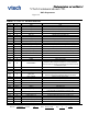
VTech proprietary and confidential VTech Communications LTD. R&D Department Figure 1-2 TABLE 1-1: VTBM-A01 PIN DESCRIPTION PIN NO. Pin TYP Pin Name Description H1 P GND GND H2 O SPK_RN Speaker output negative, right H3 O SPK_RP Speaker output positive, right H4 I MIC_BN Line input negative, channel B H5 I MIC_BP Line input positive, channel B H6 O SPK_LN Speaker output negative, left H7 O SPK_LP Speaker output positive, left H8 AIO AIO[0] Analog programmable input line 0.
VTech proprietary and confidential VTech Communications LTD. R&D Department H37 I/O PIO[18] Programmable input/output line 18.
VTech proprietary and confidential VTech Communications LTD. R&D Department excellent performance in the presence of noise enables VTBM-A01 BT Module to exceed the Bluetooth requirements for cochannel and adjacent channel rejection. 2.3 RF transmitter 2.3.1 IQ modulator The transmitter features a direct IQ modulator to minimize frequency drift during a transmit timeslot, which results in a controlled modulation index. Digital baseband transmit circuitry provides the required spectral shaping. 2.3.
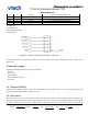
VTech proprietary and confidential VTech Communications LTD. R&D Department 4 Serial Quad I/O Flash The VTBM-A01 BT Module uses external serial flash ICs for storage of: • Device-specific data • Application • Libraries • Voice prompt files • Proprietary data The VTBM-A01 BT Module supports a 8MB 4‑bit I/O flash. Figure 4-1 Typical connection between the QCC3008 QFN and a serial flash IC 5 Serial interfaces 5.
VTech proprietary and confidential VTech Communications LTD. R&D Department PSKEY_UART_RX_PIO PIO[0] PSKEY_UART_TX_PIO PIO[1] PSKEY_UART_RTS_PIO PIO[8] (default) or PIO[16] PSKEY_UART_CTS_PIO PIO[9] (default) or PIO[17] Figure 5-1 shows the 4 signals that implement the UART function. Figure 5-1 Universal asynchronous receiver When VTBM-A01 BT Module is connected to another digital device, UART_RX and UART_TX transfer data between the 2 devices.
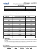
VTech proprietary and confidential VTech Communications LTD. R&D Department Parity None, Odd or Even Number of stop bits 1 or 2 Bits per byte 8 Table 5-3 lists common baud rates and their associated error values for PSKEY_UART_BITRATE. To set the UART baud rate, load PSKEY_UART_BITRATE with the number of bits per second. Table 5-3 Standard baud rates Baud rate PS Key value (bits per second) Error 1200 1200 1.73% 2400 2400 1.73% 4800 4800 1.73% 9600 9600 -0.82% 19200 19200 0.
VTech proprietary and confidential VTech Communications LTD. R&D Department The VTBM-A01 BT Module supports an I²C interface for I/O port expansion. The default assignment of the I²C interface onto the PIOs on the VTBM-A01 BT Module is: • PIO [0] is the I²C interface SCL line (AMP_I2C_SCL) • PIO [0] is the I²C interface SCL line (AMP_I2C_SCL) Alternatively, the I²C interface can be assigned to two PIOs from PIO [9:0] using PSKEY_I2C_SCL_PIO and PSKEY_I2C_SDA_PIO.
VTech proprietary and confidential VTech Communications LTD. R&D Department The terminals are open-drain outputs, so the LED must be connected from a positive supply rail to the pad in series with a current-limiting resistor. Figure 6-1 LED equivalent circuit From Figure 6-1 it is possible to derive Equation 6-1 to calculate ILED. If a known value of current is required through the LED to give a specific luminous intensity, then the value of RLED is calculated.
VTech proprietary and confidential VTech Communications LTD. R&D Department independent sample rate. Figure 7-1 VTBM-01 BT Module audio interface 7.1 Audio input and output The audio input circuitry consists of 2 independent 16-bit high-quality ADC channels: • Programmable as either stereo or dual-mono inputs. • 1 input programmable as either microphone or line input, the other as line input only. • Each channel can be connected as either single-ended or fully differential.
VTech proprietary and confidential VTech Communications LTD. R&D Department represents the left channel and channel 1 or channel B represents the right channel. 7.2.1 Audio codec block diagram Figure 7-2 Audio codec input and output stages The VTBM-A01 BT Module audio codec uses a fully differential architecture in the analog signal path. This architecture results in low common-mode-noise sensitivity and good power supply rejection while effectively doubling the signal amplitude.
VTech proprietary and confidential VTech Communications LTD. R&D Department • 16 kHz • 22.050 kHz • 24 kHz • 32 kHz • 44.1 kHz • 48 kHz 7.2.2.2 ADC audio input gain The VTBM-A01 BT Module audio input gain consists of the following components: • An analog gain stage based on a pre-amplifier and an analog gain amplifier • A digital gain stage Figure 7-3 Audio input gain 7.2.2.3 ADC pre-amplifier and analog/digital gain The gain of the ADC inputs can be configured in the range of -27 dB to 63.
VTech proprietary and confidential VTech Communications LTD. R&D Department Table 7-1 lists how the ADC digital gain selection values map to digital gain settings. Digital gain selection value ADC digital gain setting (dB) Digital gain selection value ADC digital gain setting (dB) 0 0 8 -24 1 3.5 9 -20.5 2 6 10 -18 3 9.5 11 -14.5 4 12 12 -12 5 15.5 13 -8.5 6 18 14 -6 7 21.5 15 -2.5 7.2.2.
VTech proprietary and confidential VTech Communications LTD. R&D Department • 32 kHz • 40 kHz • 44.1 kHz • 48 kHz 7.2.3.2 DAC gain The DAC outputs have two gain stages, a digital stage followed by an analog stage. The digital gain varies between -24 dB and 21.5 dB and the analog gain between -21 dB and 0 dB, giving a total range of -45 dB to 21.5 dB. Calls connected by the VM stream automatically select the distribution of gain within the DAC for best performance.
VTech proprietary and confidential VTech Communications LTD. R&D Department 7.2.3.3 DAC digital FIR filte The DAC contains an integrated digital FIR filter with the following modes: • A default long FIR filter for best performance at ≥ 44.1 kHz. • A short FIR to reduce latency. • A narrow FIR (a sharp roll-off at Nyquist) for G.722 compliance. Best for 8 kHz/16 kHz. 7.2.4 Microphone bias generator VTBM-A01 BT Module contains an independent low-noise microphone bias generator.
VTech proprietary and confidential VTech Communications LTD. R&D Department Figure 7-5 Differential input Figure 7-6 Single-ended input 7.2.6 Output stage The output stage digital circuitry converts the signal from 16 bit per sample, linear PCM of variable sampling frequency to bit stream, which is fed into the analog output circuitry. The analog output circuit comprises a DAC, a buffer with gain-setting, a low pass filter, and a class AB output stage amplifier.
VTech proprietary and confidential VTech Communications LTD. R&D Department Figure 7-7 Speaker output 7.2.7 Mono operation Mono operation is a single-channel operation of the stereo codec. The left channel represents the single mono channel for audio in and audio out. In mono operation, the right channel is the auxiliary mono channel for dual-mono channel operation. In single channel mono operation, disable the other channel to reduce power consumption. 7.2.
VTech proprietary and confidential VTech Communications LTD. R&D Department Figure 7-8 Sidetone The ADC provides simple gain to the sidetone data. The gain values range from -32.6 dB to 12.0 dB in alternating steps of 2.5 dB and 3.5 dB, see Table 7-4. Table 7-4 Sidetone gain Value Sidetone gain Value Sidetone gain 0 -32.6 dB 8 -8.5 dB 1 -30.1 dB 9 -6.0 dB 2 -26.6 dB 10 -2.5 dB 3 -24.1 dB 11 0 dB 4 -20.6 dB 12 3.5 dB 5 -18.1 dB 13 6.
VTech proprietary and confidential VTech Communications LTD. R&D Department 6 -14.5 dB 14 9.5 dB 7 -12.0 dB 15 12.0 dB 7.3 I²S1 and I²S2 interface VTBM-A01 BT Module supports I²S input and output via its two industry-standard I²S digital audio interfaces, left-justified or right-justified. NOTE • • • • • In this section, terms are defined as follows: I²S refers to the I²S1 and I²S2 interfaces. SD_IN refers to I2S1_SD_IN or I2S2_SD_IN.
VTech proprietary and confidential VTech Communications LTD. R&D Department Figure 7-9 Digital audio interface modes Table 7-5 Digital audio interface slave timing Symbol Parameter Min Typ Max Unit – SCK Frequency – – 6.2 MHz – WS Frequency – – 96 kHz tch SCK high time 80 – – ns tcl SCK low time 80 – – ns Table 7-6 I²S slave mode timing Symbol Parameter Min Typ Max Unit tssu WS valid to SCK high set- 20 up time – – ns tsh SCK high to WS invalid 2.
VTech proprietary and confidential VTech Communications LTD. R&D Department Table 7-7 I²S slave mode timing (cont.) Symbol Parameter Min Typ Max Unit tisu SD_IN valid to SCK high set-up time 20 – – ns tih SCK high to SD_IN invalid hold time 2.5 – – ns Figure 7-10 Digital audio interface slave timing Table 7-8 Digital audio interface master timing Symbol Parameter Min Typ Max Unit – SCK Frequency – – 6.
VTech proprietary and confidential VTech Communications LTD. R&D Department Table 7-10 I²S master mode timing parameters, WS and SCK as outputs (cont.) Symbol Parameter Min Typ Max Unit tisu SD_IN valid to SCK high set up time 18.44 – – ns tih SCK high to SD_IN invalid hold time 0 – – ns Figure 7-11 Digital audio interface master timing 8 Power control 8.1 Switch-mode regulators For greater power efficiency, the VTBM-A01 BT Module contains 2 switch-mode regulators: • One to generate a 1.
VTech proprietary and confidential VTech Communications LTD. R&D Department The RST# pin is an active low reset. Assert the reset signal for a period > 5 ms to ensure a full reset.At reset the digital I/O pins are set to inputs for bidirectional pins and outputs are set to tristate.
VTech proprietary and confidential VTech Communications LTD. R&D Department Figure 9-1 shows the mode-to-mode transition voltages. 9.1 External mode The external mode is for charging higher capacity batteries using an external pass device. The current is controlled by sinking a varying current into the CHG_EXT pin, and the current is determined by measuring the voltage drop across a resistor, Rsense, connected in series with the external pass device.
VTech proprietary and confidential VTech Communications LTD. R&D Department 10 Electrical characteristic 10.1 Absolute maximum rating Rating Min Storage temperature -40 Max Unit ℃ 105 Supply voltage 5 V (USB VBUS) VCHG -0.40 6.50 V VDD_USB -0.40 3.60 V LED[2:0] -0.40 4.40 V SMP_VBAT -0.40 4.40 V VBAT_SENSE -0.40 4.40 V VREGENABLE -0.40 4.40 V PIO -0.40 3.60 V Unit 3.3V Battery PIO NOTE Voltage must not exceed 3.6 V on any I/O. 10.
VTech proprietary and confidential VTech Communications LTD. R&D Department 10.3 Input/Output terminal characteristic For all I/O terminal characteristics: • Current drawn into a pin is defined as positive. • Current supplied out of a pin is defined as negative. 10.3.1 LED driver pads LED driver pads Min Typ Max Unit High impedance state – – 5 µA Current sink state – – 10 mA IPAD = 10 mA – – 0.55 V VOL output logic level low – 0 – V VOH output logic level high – 0.
VTech proprietary and confidential VTech Communications LTD. R&D Department Vfast rising threshold trim step size - 0.1 - V Vfast falling threshold - 2.8 - V Fast charge mode Min Typ Max Unit 194 200 206 mA - 10 - mA 50- - 100 % Charge current step size - 10 - mA Vfloat threshold, 4.20 V 4.16 4.20 4.24 V Vfloat threshold, 4.35 V 4.31 4.35 4.
VTech proprietary and confidential VTech Communications LTD. R&D Department Voltage on CHG_EXT 0 – 6.50 V External pass device hfe – 50 – – Sense voltage, between VBAT_SENSE and VBAT at maximum current 195 200 205 mV NOTE In the external mode, the battery charger meets all the previous charger electrical characteristics and the additional or superseded electrical characteristics are listed in this table. 10.5 System current consumption System Status Typ. Max.
VTech proprietary and confidential VTech Communications LTD. R&D Department Side View 12 Module photo Top View (PCB Ant Version) Top View (External Ant Version) 13 Recommended Reflow Profile The document is VTech’s proprietary information, Please do not disclose to third party without VTech’s consent Ref. No.