
Product Info


VTech proprietary and confidential
VTech Communications LTD.
R&D Department
The document is VTech’s proprietary information, Please do not disclose to third party without VTech’s consent
Ref. No.: 20191009 Version: 01 Date: 09 Oct, 2019 Page 25 of 33
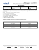
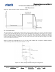
The RST# pin is an active low reset. Assert the reset signal for a period > 5 ms to ensure a full reset.At reset the digital I/O
pins are set to inputs for bidirectional pins and outputs are set to tristate.
NOTE Reset can also be triggered by a UART break symbol if:
• Host interface is any UART transport
And
• PSKEY_HOSTIO_UART_RESET_TIMEOUT is set to a value more than 1000 A reboot function is also
available under software control.
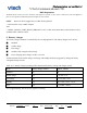
9 Battery charger
The battery charger hardware is controlled by the on-chip application. The battery charger has 5 modes:
■ Disabled
■ Trickle charge
■ Fast charge
■ Standby: fully charged or float charge
■ Error: charging input voltage, VCHG, is too low
Transitions between the trickle charge, fast charge and standby modes are triggered by changes in battery
voltageand charger current.
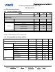
Table 10-1 Battery charger operating modes determined by battery voltage and charger current
Mode
Battery charger enabled
VBAT_SENSE
Disabled
No
X
Trickle charge
Yes
> 0 and < Vfast
Fast charge
Yes
> Vfast and < Vfloat
Standby
Yes
Iterm and > (Vfloat - Vhyst)
Error
Yes
> (VCHG - 50mV)
Iterm is approximately 10% of Ifast for a given Ifast setting