
Product Info


VTech proprietary and confidential
VTech Communications LTD.
R&D Department
The document is VTech’s proprietary information, Please do not disclose to third party without VTech’s consent
Ref. No.: 20191009 Version: 01 Date: 09 Oct, 2019 Page 4 of 33
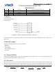
Figure 1-2
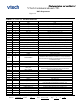
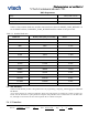
TABLE 1-1: VTBM-A01 PIN DESCRIPTION
PIN NO.
Pin TYP
Pin Name
Description
H1
P
GND
GND
H2
O
SPK_RN
Speaker output negative, right
H3
O
SPK_RP
Speaker output positive, right
H4
I
MIC_BN
Line input negative, channel B
H5
I
MIC_BP
Line input positive, channel B
H6
O
SPK_LN
Speaker output negative, left
H7
O
SPK_LP
Speaker output positive, left
H8
AIO
AIO[0]
Analog programmable input line 0.
H9
I/O
PIO[4]/I2S1_WS/SPI_CS#
Programmable input/output line 4./SPI_CS#/I2S1_WS
H10
I/O
PIO[16]/UART_RTS#
Programmable input/output line 16./UART_RTS
H11
I/O
PIO[3]/I2S1_SD_OUT/SPI_MISO
Programmable input/output line 3./SPI_MISO/I2S1_SD_OUT
H12
SPI_MOSI
SPI_MOSI
SPI_MOSI: Debug SPI data input
H13
I/O
PIO[17]/UART_CTS#
Programmable input/output line 17./UART_CTS
H14
I/O
PIO[5]/I2S1_SCK_SPI_CLK
Programmable input/output line 5./SPI_CLK/I2S1_SCK
H15
P
GND
GND
H16
I
RST
Reset if low. Pull low for minimum 5 ms to cause a reset.
H17
O
LED[1]
Open-drain output
H18
O
LED[0]
Open-drain output
H19
P
VREGENABLE
Regulator enable and multifunction button. A high input
(tolerant to VBAT voltages) enables the on-chip regulators,
which can then be latched on internally and the button used as
a multifunction input.
H20
P
VCHG
Charger input.
H21
P
VBAT
Battery positive terminal.
H22
P
SMPS_1.8V
1.8V switch-mode power regulator output
H23
P
CHG_EXT
External battery charger transistor base control when using
external charger boost. Otherwise leave unconnected
H24
I
VBAT_SENSE
Battery charger sense input.
H25
P
SMPS_1.35V
1.35V switch-mode power regulator output
H26
P
GND
GND
H27
P
GND
GND
H28
USB_N
USB_N
USB data minus
H29
USB_P
USB_P
USB data plus
H30
I/O
PIO[7]/I2S2_WS
Programmable input/output line 7./I2S2_WS
H31
I/O
PIO[9]/I2S2_SCK/UART_CTS#
Programmable input/output line 9./UART_CTS
H32
I/O
PIO[0]/UART_RX
Programmable input/output line 0./UART_RX
H33
I/O
PIO[1]/UART_TX
Programmable input/output line 1./UART_TX
H34
I/O
PIO[8]/I2S2_SD_IN/UART_RTS#
Programmable input/output line 8./UART_RTS
H35
I/O
PIO[6]/I2S2_SD_OUT
Programmable input/output line 6./I2S2_SD_OUT
H36
I/O
PIO[21]
Programmable input/output line 21.