
Instructions / Assembly

01 02
03 04
This equipment has been tested and found to comply with the limits for a Class B digital device,
pursuant to Part 15 of the FCC Rules. These limits are designed to provide reasonable protection
against harmful interference when the equipment is operated in a commercial environment. This
equipment generates uses and can radiate radio frequency energy and, if not installed and used in
accordance with the instructions, may cause harmful interference to radio communications.
The antennas used for this VueBell unit must be installed to provide a separation distance of at least
20 cm from all persons and must not be co-located for operating in conjunction with any other
antenna or VueBell unit.
Except for the operations of law enforcement officers conducted under lawful authority, no person
shall use, either directly or indirectly, a device operated pursuant to the provision of this part for the
purpose of overhearing or recording the private conversations of other unless such use is authorized
by all of the parties engaging in the conversation.
The VueBell Unit will remain in a standby state with all LED indicators in the off state if no activity is
detected except for the built-in ePIR sensor which is constantly monitoring for activity day or night.
Once activity has been detected within 10’ all monitoring function and features become active. The
built in day and night vision camera in VueBell will begin to take snapshots of the event. Photos of the
event will be saved on a cloud storage service for user access. The event will trigger a notification on
the user’s mobile device which will lead them directly to the photos.
When a homeowner, visitor, neighbor, or delivery person approaches VueBell, ePIR captures the
event and triggers the camera and the bell-shaped touch button will light up (Blue). The bell shaped
button is press to ring the bell, it will then send a signal to the smart mobile device and the indoor
music chime to sound. User will receive a notification on their smart phone/mobile device with a
picture of the event and with the option to start a live chat with the visitor through VueBell. User will
also be able to unlock the door through VueBell application (Optional).
FCC (USA) 15.9 prohibition against eavesdropping
FCC radiation exposure statement
Warning
Operation and features of VueBell
Download VueBell APP from APP store or Google play market.
APP Set-up
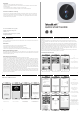
Packing list
Names for parts
Wide angle HD camera
PIR sensor
Microphone
Touch button
Speaker
Front cover and back cover hook
VueBell unit front side Wall mounting plate
LED
Holes for screws
Hole for wire
Reset
Front cover and back cover hook
1. Please note that installation tools such as power drills and screwdrivers are required for
installation but not supplied in this package.
2. Please try to avoid installing the unit close to metal frames since metal can absorbs radio waves
and weaken the radio reception
3. Do not install the product in extreme temperature conditions or humid environments (such as
kitchen or bathroom).
4. The range of operating voltage from the power supply/transformer: 8-24VAC, 9-36VDC, and
not polarity required.
5. Please install unit where it does not directly place the CCD camera to the sunlight
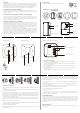
VueBell unit setup terminal and reference
Read before Installing
Connect with AC/DC power source
05 06
Installation Procedures
1.Replace outdated doorbell system using the existing power transformer and wire/cable by mounting it at the
same location:
-Turn off the power at the main circuit breaker panel or Fuse box. Remove existing doorbell button connect
new VueBell using the existing wire/cable.
-Turn the power on and see if VueBell powers up. If you are replacing an old coil-type bell/chime, it should
work without doing any further reconfiguration. If you are replacing a electronic musical bell/chime you will
need to short the two wires connecting power to the bell by connecting them together with a wire nut, or tie
both wires together on one wire terminal. This will bypass the existing doorbell/chime and directly connect the
VueBell with existing transformer/power supply.
-An additional indoor musical chime (provided in the package) can be installed into the AC power outlet to
provide sounds when the VuBell is activated. To set this up please follow setup procedures by referring to
video:
https://www.youtube.com/watch?v=_Aq15QrxV8s
2. For new installation run a 2 conductors wire #22-18 AWG US/standard wire size connected to an AC power
transformer (8-24VAC) or DC adapter (9-36VDC).
Below are optional VueBell connections:
a) VueBell can be connected to your facility/house existing Alarm Control using the AUX 12VDC power, or PIR
detector/Keypad power e.g.
②① ④③
⑤
Indoor Music Chime
Remove the battery cover and insert 2×1.5V AA batteries; Ensure battery polarity match the internal
markings. Fix a screw on the wall. Then hang the Indoor Music Chime by the hole at the back of the unit.
Avoid positioning on UPVC Frames, above heat sources (e.g. radiator) or in damp areas such as a kitchen
or bathroom. Important: Test the Indoor Music Chime before drilling any holes to ensure it is within
operating range. Note: As an alternative, the Indoor Music Chime can also be placed on the flat surface,
such as table.
Melody Selection
There is a melody selector located at right side of the Indoor Music Chime. Press the selector to change
different melody.
5. Quick start guide3. Accessories1. VueBell unit 4. location label
screw hole
Drilling template
Indoor Music Chime
back side
Hanging Hole
Speaker
Battery Cover
Receiver front side
Volume Button
Melody Selector
2. indoor receiver
b) VueBell can be connected to your standard CCTV Camera 12VDC or 24VAC power supply/transformer.
c) VueBell can be connected to a 12 to 24 AC power wall adaptor/transformer outlet, use the purchase link
below to see the recommended VueBell mounting location. Then connect the power wires to the unit
terminal to start initial setup.
http:// www.ebay.com /itm /12VDC-Power-Supply-Adaptor-AC-DC-Switched-Digital-Charger-
/120767424257
3. Once above steps and set-up are done, users can mount the VueBell by using all provided installation
kit. Please refer to initial setup:
①and② -Connect each of the two wires to one of the top two screws (which marked “AC/DC Power) on the
back of VueBell. The blue-colored bell-shaped touch pattern will light up.
③ -Place the VueBell on the mounting bracket (back cover).
④ -Tighten the security screws
⑤ - Just in case you have two old bell buttons on your front door and back door, follow the same
procedures and ignore the second bell button. If you have two bells and would like to install your second
VueBell, simply repeat step 3 for installation.