INSTALLATION & OPERATION MANUAL GAS RESTAURANT RANGES 90 SERIES AND VG SERIES MODEL 24L 36L 481L 148L 60L 260L VG24 VG36 VG60 VG260 ML-52947 ML-52948 ML-52950 ML-52951 ML-52952 ML-52954 ML-114553 ML-114554 ML-114555 ML-114557 PRIOR MLS COVERED IN THE CATALOG 48L 160L VG48 VG160 ML-52949 ML-52953 ML-114957 ML-114556 MODEL VG36 MODEL 36L For additional information on Vulcan-Hart or to locate an authorized parts and service provider in your area, visit our website at www.vulcanhart.
IMPORTANT FOR YOUR SAFETY THIS MANUAL HAS BEEN PREPARED FOR PERSONNEL QUALIFIED TO INSTALL GAS EQUIPMENT, WHO SHOULD PERFORM THE INITIAL FIELD START-UP AND ADJUSTMENTS OF THE EQUIPMENT COVERED BY THIS MANUAL. POST IN A PROMINENT LOCATION THE INSTRUCTIONS TO BE FOLLOWED IN THE EVENT THE SMELL OF GAS IS DETECTED. THIS INFORMATION CAN BE OBTAINED FROM THE LOCAL GAS SUPPLIER.
TABLE OF CONTENTS GAS RESTAURANT RANGE MODELS . . . . . . . . . . . . . . . . . . . . . . . . . . . . . . . . . . . . . . . . . . . . . . 4 OPTIONAL FIELD INSTALLABLE ACCESSORIES . . . . . . . . . . . . . . . . . . . . . . . . . . . . . . . . . . . . 5 GENERAL . . . . . . . . . . . . . . . . . . . . . . . . . . . . . . . . . . . . . . . . . . . . . . . . . . . . . . . . . . . . . . . . . . . . . 6 INSTALLATION . . . . . . . . . . . . . . . . . . . . . . . . . . . . . . . . . . . . . . . . . . . . . . . . .
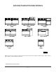
GAS RESTAURANT RANGE MODELS 60L, 60LC, 60LCC VG60 * 48L/VG48 260L, 260LC, 260LCC VG260 148L, 148LC 36L, 36LC VG36 * 160L, 160LC VG160 481L, 481LC 24L VG24 PL-53007 NOTE: References to 90 Series Convection Ovens will include only the following models: 36LC, *148LC, 481LC, 60LC, 60LCC, *160LC, 260LC or 260LCC. * Indicates discontinued model.
OPTIONAL FIELD INSTALLABLE ACCESSORIES DESCRIPTION OPTIONS Flue Devices 1. Stainless steel backsplash with plate shelf. 2. Stainless steel 11" (27.9 cm) low riser. Flex Hose and Quick Disconnects 1. 2. 3. Oven Racks 1. 1 extra rack – standard oven style. 2. 1 extra rack – convection oven style. /4" (19 mm) flex hose/disconnect – 3 ft. (914.4 mm) long. /4" (19 mm) flex hose/disconnect – 4 ft. (1219.2 mm) long. 3 /4" (19 mm) flex hose/disconnect – 5 ft. (1524 mm) long.
Installation, Operation and Care of GAS RESTAURANT RANGES 90 SERIES AND VG SERIES PLEASE KEEP THIS MANUAL FOR FUTURE REFERENCE GENERAL Vulcan ranges and ovens are produced with quality workmanship and material. Proper installation, usage and maintenance of your range will result in many years of satisfactory performance. Vulcan-Hart suggests that you thoroughly read this entire manual and carefully follow all of the instructions provided.
INSTALLATION CODES AND STANDARDS Ranges must be installed in accordance with: In the United States of America 1. State and local codes. 2. National Fuel Gas Code, ANSI-Z223.1 (latest edition). Copies may be obtained from The American Gas Association, Inc., 1515 Wilson Blvd., Arlington, VA 22209. 3. National Electrical Code ANSI/NFPA-70 (latest edition). Copies may be obtained from The National Fire Protection Association, Batterymarch Park, Quincy, MA 02269. In Canada 1. Local codes. 2. CAN/CGA-B149.
Bumper Bars (Convection Oven Ranges Only) CAUTION: Failure to install bumper bars may cause motor damage and will void the warranty. Remove existing #10 screws. Position bumper bars (supplied) as shown. Replace #10 screws and secure bumper bars (Fig. 2). REAR VIEW OF RANGE NOTES: 1. Bumper bars required for all Convection Oven Ranges. 2. Restraining device required for all ranges with casters. 3. Restraining device not supplied by unit manufacturer.
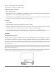
Fig. 3 The Restaurant Range griddle top section utilizes a two-fold baffle assembly to support the composite/mortar fire bricks. There will always be only one small 61/2" (165 mm) wide baffle assembly with every griddle top order. There will be at least one 97/ 8" (251 mm) wide baffle assembly per griddle, possibly more, depending on the griddle width. The 61/2" (165 mm) wide baffle will utilize two 10" x 4" (254 x 101.6 mm), and two 7" x 4" (177.8 x 101.6 mm) brick sets.
4. Exercise caution when placing brick in a thermostatically controlled griddle section. DO NOT hit thermostat bulb while installing bricks. The thermostat bulb is a sensitive device and may be easily knocked out of adjustment. Into the 61/2" (165 mm) wide baffle, install: a. Two 10" x 4" (254 x 101.6 mm) bricks, placing the miter edge, one to each side of the front burner baffle area (Fig. 4). b. Two 7" x 4" (177.8 x 101.6 mm) bricks, one to each side of the rear burner baffle area (Fig. 4). Fig. 4 5.
7. Check to ensure that all bricks and burners are secure. Carefully replace the griddle top section. When replacing griddle top section, be sure that the griddle capillary and bulb(s) are not in a position to be crushed. Gently pull the griddle capillary towards the front of the range and out from under the griddle area.
Backsplash Component Parts MODELS 24L/VG24 36L/VG36 *48L, 481L, & *148L *VG48 60L & *160L VG60/*160 260L/VG260 Std. 23" (58.4 cm) High Backsplash (1) Std. 23" (58.4 cm) High Backsplash (1) Std. 23" (58.4 cm) High Backsplash (1) Std. 23" (58.4 cm) High Backsplash (1) Std. 23" (58.
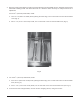
5. It may be necessary to pull the heat shield bottom out slightly in order to clear the oven flue box area. Be sure the backsplash is resting evenly and the channel holes are lining up with the holes provided in the rightand left-hand body side (Fig’s. 7 & 8). Fig. 7 Fig. 8 6. Install eight #10 sheet metal screws (4 to each channel leg) (Fig. 9). Fig.
7. From the front, install four 1/4-20 x 25/16" (58.7 mm) long machine screws and secure bolts with locknuts. Do not tighten the screws all the way down. Leave about 1/ 4" (6.3 mm) of play in each screw (Fig. 10). 8. Lift the shelf up and slide the shelf into position over the screw heads (Fig. 11). 9. Tighten the four screws to secure the shelf. Fig. 10 Fig. 11 LEVELING Check the leveling of the range. Place a carpenter’s level inside the oven cavity across the oven rack(s).
As of 7/11/90, the gas pressure regulator is NOT factory installed. The regulator for this gas type is sealed within a plastic bag attached to the oven rack inside the oven cavity. This regulator must be field installed by a qualified installer. Natural gas regulators are preset for 3.7" W.C. (Water Column) (.92 kPa); propane gas regulators for 10.0" W.C. (2.5 kPa) 1. 2. 3. 4. Locate 3/ 4" (19 mm) gas connection pipe extending from rear of range. Cover pipe threads with leak sealant.
FLUE CONNECTIONS DO NOT obstruct the flow of flue gases from the flue located on the rear of the range. It is recommended that the flue gases be ventilated to the outside of the building through a ventilation system installed by qualified personnel. From the termination of the flue to the filters of the hood venting system, a minimum clearance of 18" (457 mm) must be maintained.
OPERATION WARNING: THE RANGE AND ITS PARTS ARE HOT. BE VERY CAREFUL WHEN OPERATING, CLEANING OR SERVICING THE RANGE. CONTROLS THERMOSTAT DIAL - STANDARD OVEN — Allows operator to regulate oven temperature from low to 500°F (260°C). THERMOSTAT DIAL - CONVECTION OVEN — Snap-acting type control which allows operator to regulate oven temperature from 150°F to 500°F (65.5°C to 260°C). OPEN TOP BURNER KNOB STANDARD AND CONVECTION OVENS — Regulates gas flow to top burners.
Hot Top and Griddle Top Burners 1. Turn main gas supply ON. 2. Wait 30 seconds and, using a taper, light the hot top or griddle top pilot (Fig. 13). Shown with old style burner knobs New style burner knobs effective 1/98 Fig. 13 3. If pilot fails to light, turn main gas supply OFF. Wait 5 minutes and repeat the above procedures. 4. Turn one hot top or griddle top burner valve ON to remove air from the gas line. Turn burner valve OFF when gas begins to flow.
3. If pilot fails to light, turn main gas supply OFF. Wait 5 minutes and repeat the above procedures. 4. Turn one open top burner valve ON to remove air from the gas line. Turn burner OFF when gas begins to flow. Nightly Shutdown: Turn burner valve OFF; pilot will remain lit. Complete Shutdown 1. Turn burner valve OFF; pilot will remain lit. 2. Turn main gas supply OFF. Broiler/Griddle 1. Turn main gas supply ON. 2 Wait 30 seconds and, using a taper, light broiler/griddle pilot (see Fig. 13). 3.
3. After pilot is lit, turn the thermostat to the desired setting. Nightly Shutdown: Turn oven thermostat OFF. Complete Shutdown 1. Turn oven thermostat OFF. 2. Turn main gas supply OFF. Standard Oven with Spark Ignition (Fig. 17) 1. Move toggle switch to ON position. Oven On Light will illuminate. The oven pilot will automatically light. 2. Once the oven pilot is established, the oven READY light will illuminate. 3. Set oven thermostat to desired temperature.
4. If pilot fails to light, turn main gas supply OFF. Wait 5 minutes and repeat Steps 2 and 3. 5. After pilot is lit, push the power switch ON and turn the thermostat to the desired setting. Nightly Shutdown: Turn the power switch OFF and the thermostat to 0 degrees. Complete Shutdown 1. 2. 3. 4. Push power switch OFF. Turn red gas valve OFF (behind kick panel). Turn main gas supply OFF. Disconnect electrical supply cord. Fig. 18 Fig. 19 Convection (Snorkel®) Oven With Spark Ignition (Fig.
1. Move rocker switch to ON position (oven ON light will illuminate). The oven pilot will automatically light. 2. Once the oven pilot is established, the oven READY light will illuminate. 3. Set oven thermostat to desired temperature. (The thermostat light will illuminate. This indicates that the thermostat is calling for heat.) The convection oven thermostat must be ON and calling for heat for the oven pilot to light. Nightly Shutdown: Push rocker switch and turn all knobs to the OFF position.
INSERTING AND REMOVING STANDARD AND CONVECTION OVEN RACKS The oven rack has a stop to keep the rack from being pulled all the way out when unloading product. To install rack, place rack along side of top of side liner runners and slide rack completely to the rear of the oven compartment until rack drops into place (Fig’s. 21 & 22). Fig. 21 Fig. 22 To remove rack, reverse the procedure above by raising rear of oven rack stop above runner and pulling rack forward (Fig. 23). Fig.
PREHEATING Standard Oven Turn thermostat control to the desired cooking temperature and preheat oven for 25 minutes. To save on gas consumption, do not operate oven at maximum heat when it is not necessary. Turn thermostat down to 250°F (121°C) or OFF when oven is not in use or during idle cooking periods. Convection Oven (90 Series Only) With power switch in the ON position, turn oven thermostat knob to the proper cooking temperature and allow oven to preheat for 15 minutes.
COOKING CHART Recommended temperatures and times are intended as a guide only. Adjustments must be made to compensate for elevation, variations in recipes, ingredients, preparation and personal preference on product appearance. Meat roasting is most satisfactory at temperatures of 225°F to 325°F (107°C to 162.7°C) for beef, lamb, poultry and ham, and 325°F (162.7°C) for fresh pork as recommended by USDA and American Meat Institute. A pan, approximately 12" x 20" x 1" (304.8 x 508 x 25.
TEMPERATURE APPROXIMATE TIME (MIN.) 300 to 325°F/148.9 to 162.8°C 15 to 20 315 to 340°F/157.2 to 171°C 20 to 30 Cup Cakes 350 to 400°F/176.7 to 204.4°C 6 to 12 Frozen Fruit Pies 350 to 375°F/176.7 to 190.5°C 30 to 45 Pumpkin or Custard Pies 300 to 350°F/148.9 to 176.7°C 30 to 45 Cobblers 12 x 18 x 2" or 12 x 20 x 21/2" pans (304.8 x 661 x 50.8 mm or 304.8 x 508 x 63.5 mm) 350 to 400°F/176.7 to 204.4°C 30 to 45 Meringue Pies 350 to 425°F/176.7 to 218.
OVEN BROILING OR FRYING TEMPERATURE APPROXIMATE TIME (MIN.) Hamburger Patties 8 per lb. (0.5 kg) - Med. well done 6 per lb. (0.5 kg) 4 per lb. (0.5 kg) 400 to 450°F/204.4 to 232.2°C 400 to 450°F/204.4 to 232.2°C 375 to 385°F/190.5 to 196°C 5 to 6 7 to 10 8 to 12 Fish Sticks & Portions Frozen bread. - 1 oz. (28.3 grams) 21/2 to 3 oz. (70.8 to 85 grams) 350 to 400°F/176.7 to 204.4°C 350 to 375°F/176.7 to 190.5°C 6 to 10 8 to 15 Chicken Pieces Broiled or Oven Fried 2 to 21/2 lbs. (0.9 to 1.
MISCELLANEOUS PRODUCTS TEMPERATURE APPROXIMATE TIME (MIN.) 400 to 450°F/204.4 to 232.2°C 400 to 450°F/204.4 to 232.2°C 400 to 450°F/204.4 to 232.2°C 25 to 35 35 to 45 40 to 60 425 to 475°F/218.3 to 246°C 5 to 10 400 to 425°F/204.4 to 218.3°C 8 to 10 PRODUCT Baked Potatoes 120 count per 50 lbs (22.7 kg) 100 count per 50 lbs. (22.7 kg) 80 count per 50 lbs. (22.
Clean oven and oven door daily, especially if fruit pies or tomato sauces were baked, meats roasted, and if there have been spillovers. After processing some foods at low temperatures, odors may linger in the oven. These odors may be cleared by setting the thermostat at 500°F (260°C) and allowing the oven to operate unloaded for 30 to 45 minutes. Empty the broiler grease pan/trough daily or as often as necessary. CAUTION: Remove the grease pan/trough slowly and be careful of liquid wave action.
Daily: Thoroughly clean backsplash, sides and front. Remove grease pan, empty and wash out in the same manner as any ordinary cooking utensil. Clean griddle surface thoroughly. If necessary, use a griddle stone, wire brush or steel wool over the surface. Rub with the grain of the metal while still warm. A detergent may be used on the plate surface to help clean it, but the cleaner must be thoroughly removed.
MAINTENANCE WARNING: THE RANGE AND ITS PARTS ARE HOT. BE VERY CAREFUL WHEN OPERATING, CLEANING OR SERVICING THE RANGE. LUBRICATION All Vulcan convection oven motors are permanently lubricated and require no additional maintenance. OVEN DOOR GASKET REPLACEMENT - CONVECTION OVEN (90 SERIES) ONLY To remove the old gasket, gently pry the arrow-like gasket pins from the oven front frame using a standard screwdriver.
TROUBLESHOOTING GUIDE STANDARD AND CONVECTION OVEN RESTAURANT RANGE OVEN PROBLEM CAUSES 1. Too much bottom heat a) b) c) d) e) 1a. Too low temperature 1b. Side burning 1c. Too much top heat Insufficient ventilation Improper fluing Improper thermostat bypass setting Thermostat out of calibration Fluctuating gas pressure 2. Uneven bake side to side a) Not level side to side b) Oven burner, bottom or baffles improperly installed c) Warped pans 3.