SERVICE MANUAL Heavy Duty Gas Griddles MODEL MLS 924RE ML-135221-00G24 936RE ML-135222-00G36 948RE ML-135223-00G48 960RE ML-135224-00G60 972RE ML-135225-00G72 www.vulcanhart.com 924RE MODELS AGE24 ITW Food Equipment Group, LLC 3600 North Point Blvd. Baltimore, MD 21222 MLS AGE24 ML-135226-00G24 AGE36 ML-135227-00G36 AGE48 ML-135228-00G48 AGE60 ML-135229-00G60 AGE72 ML-135230-00G72 www.wolfrange.com FORM F-35628 (Rev.
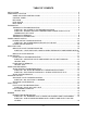
TABLE OF CONENTS INSTALLATION ........................................................................................................................... 4 COMPONENT LOCATION .......................................................................................................................5 948RE AND AGE48 CONTROL PANEL .............................................................................. 5 CONTROL PANEL ...........................................................................................
SYMPTOM – ONE BURNER HAS A DELAYED IGNITION; A SEVERAL SECOND LAPSE BETWEEN THE INDICATOR LIGHT TURING ON AND WHEN THE BURNER ACTUALLY LIGHTS. ..................................................................................................................................16 BURNER REMOVAL ....................................................................................................... 16 BURNER ADJUSTMENT ................................................................................................
GENERAL INTRODUCTION This manual is prepared for the use of trained service technicians and should only be used by those who are properly qualified. This manual is not intended to be all encompassing. You should read, in it's entirety, the repair procedure you wish to perform to determine if you have the necessary tools, instruments and skills required to perform the procedure. Procedures for which you do not have the necessary tools, instruments and skills should not be attempted.
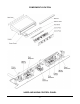
COMPONENT LOCATION 948RE AND AGE48 CONTROL PANEL -5-
CONTROL PANEL Disconnect the electrical power and follow lockout / tagout procedures The Control Panel holds the thermostats, indicator lights and power switch, and is connected to the Control Plate with a Panel Connector 1. Remove the four screws securing the control panel. There are two screws at each end of the panel. 2. Pull the control panel forward and disconnect the electrical panel connector near the right end. 3. Reverse the procedure to install.
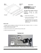
HEAT SHIELD Disconnect the electrical power and follow lockout / tagout procedures The heat shield protects the electrical components and should only be temporarily removed for easier replacement of some the control components. 1. Remove the control panel. 2. Remove screws along the top edge that secure the heat shield. 3. The shield clamps on the front of the chassis and can be removed by grasping the top of the shield and pulling forward.
Disconnect the electrical power and follow lockout / tagout procedures THERMOSTAT TROUBLESHOOTING SYMPTOM – NO POWER TO THE BURNER SOLENOID 1. Check for loose or excessively greasy/dirty connections at terminals 2. Check for continuity/resistance between the two thermostat terminals with wires disconnected A. If you get continuity/resistance with the thermostat off or open – replace thermostat B. If you do not get continuity or resistance with thermostat on or closed – replace thermostat 3.
THERMOSTAT CALIBRATION 1. Each thermostat controls a 12” zone of the griddle. Using a Surface Probe temperature measurement device, observe the temperatures at the center points of the cooking zones. These points are located by starting 6” from the side splash (left or right) and every 12” across the width of the griddle, with all points located 12” back from the front edge of the griddle plate. Use of infrared thermometers is not recommended.
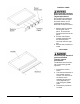
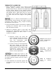
TEMPERATURE DIAL KNOB POWER SWITCH INDICATOR LIGHT KNOB GUARD (OPTIONAL) POWER ON/OFF SWITCH The Power Switch controls the power supply to all other electronic components. Disconnect the electrical power and follow lockout / tagout procedures POWER SWITCH TROUBLESHOOTING SYMPTOM – NO POWER BEING SUPPLIED TO THE UNIT 1. Check for loose or excessively greasy/dirty connections at terminals. 1. With power wires disconnected check for continuity/resistance between the 1 and 2 terminals A.
A. If no voltage – check wiring for short or break and check thermostat B. If you have 120V – replace indicator light. Disconnect the electrical power and follow lockout / tagout procedures INDICATOR LIGHT REMOVAL 1. Remove the control panel 2. Label and disconnect wires to the light 3. Squeeze the light retainers and slide the light out through the front of the control panel 4. Reverse the procedures to install and check for proper operation FLAME SWITCH The flame switch is a normally open sensor.
Disconnect the electrical power and follow lockout / tagout procedures FLAME SWITCH TROUBLESHOOTING SYMPTOM – INDICATOR LIGHTS, THERMOSTATS AND BURNER VALVES NOT WORKING 1. Check for loose or excessively greasy/dirty terminal connections 2. Check that flame switch probe is fully engulfed in the pilot flame and glowing cherry red. A. If sensor is not glowing red and/or not engulfed in pilot flame 1. Check gas pressure and adjust pilot flame for proper impingement; clean pilot if necessary 2.
Disconnect the electrical power and follow lockout / tagout procedures SPARK IGNITOR TROUBLESHOOTING SYMPTOM – NO SPARK BETWEEN PILOT HEAD AND ELECTRODE 1. Check for loose or greasy/dirty connections at all terminals (including electrode wire) 2. Check for 120 voltage from L1 terminal to ground a. If no voltage check on/off switch and wiring for shorts or breaks 3. Check that ground spade is securely attached to mounting bracket. 4.
Disconnect the electrical power and follow lockout / tagout procedures SOLENOID VALVE TROUBLESHOOTING SYMPTOM – NO GAS FLOW TO BURNER 1. Check terminals for loose or greasy/dirty connections 2. Check gas pressure – check for orifice obstructions. 3. With thermostat, indicator light and power switch on – check for 120 voltage between the two terminals on the solenoid. A. On pilot solenoid if no voltage – check wiring and on/off power switch B.
PILOT ASSEMBLY REMOVAL Disconnect the electrical power and follow lockout / tagout procedures Shut off gas supply 1. Remove control panel and heat shield 2. Reaching underneath the front of the unit, remove the pilot tube fitting and disengage the pilot tube from the pilot. 3. Pull the flame switch probe straight down and out from the snap in retainer. 4.
Disconnect the electrical power and follow lockout / tagout procedures BURNER TROUBLESHOOTING SYMPTOM – ALL BURNERS HAVE A LOWER OR HIGHER FLAME THAN NORMAL. 1. Check gas pressure SYMPTOM – ONE OR MORE BURNERS HAVE LOWER FLAME LEVEL THAN THE OTHERS. 1. Check gas pressure 2. Check burner orifice for obstructions 3. Adjust burner air shutter 4. Check solenoid valve SYMPTOM – ONE BURNER HAS A DELAYED IGNITION; A SEVERAL SECOND LAPSE BETWEEN THE INDICATOR LIGHT TURING ON AND WHEN THE BURNER ACTUALLY LIGHTS. 1.
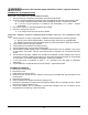
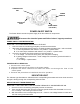
BURNER CLIP (UNDERNEATH) FLASH TUBE PILOT ASSY IGNITION PORTS AIR SHUTTER ORIFICE MAIN BURNERS These photos are for reference – it should not be necessary to remove the griddle top to perform the procedures listed in this manual. GAS REGULATOR VENT LIMITER REGULATOR INSTALLED UPRIGHT POSITION ADJUSTMENT COVER IN A HORIZONTAL, - 17 - The 900RE and AGE series units must have an exterior machine gas regulator installed. The units are shipped with a regulator that has a vent limiter.
REGULATOR TROUBLESHOOTING SYMPTOM – UNIT WILL NOT MAINTAIN CONSISTENT PRESSURE 1. Check that vent limiter is not clogged by grease and debris 2. Check store gas pressure before regulator with all equipment on that line turned on and consuming gas A. For natural gas should be between 7” and 14” W.C. B. For propane gas should be between 12” and 14” W.C. 3. Check that regulator is installed in a horizontal, upright position 4.
SEQUENCE OF OPERATION Operation is the same for all size griddles. The neutral wire from the power source is directly connected to a terminal on each thermostat, the N terminal on each ignition module and one terminal on the pilot solenoid. 1. The power on/off switch is set to the ON position. 2. Voltage is applied to the following terminals A. Terminal L1 on each igniter module – turning the module on B. The NO terminal of each flame switch C.
WIRING DIAGRAMS WIRING DIAGRAM – 24-INCH GRIDDLE - 20 -
WIRING DIAGRAM – 36-INCH GRIDDLE - 21 -
WIRING DIAGRAM – 48-INCH GRIDDLE - 22 -
WIRING DIAGRAM – 60-INCH GRIDDLE - 23 -
WIRING DIAGRAM – 72-INCH GRIDDLE - 24 -