INSTALLATION & OPERATION MANUAL FOR Heavy Duty Gas Griddles MODEL MLS 924RE ML-135221-00G24 936RE ML-135222-00G36 948RE ML-135223-00G48 960RE ML-135224-00G60 972RE ML-135225-00G72 www.vulcanhart.com MODELS MLS AGE24 ML-135226-00G24 AGE36 ML-135227-00G36 AGE48 ML-135228-00G48 AGE60 ML-135229-00G60 AGE72 ML-135230-00G72 www.wolfrange.
IMPORTANT FOR YOUR SAFETY THIS MANUAL HAS BEEN PREPARED FOR PERSONNEL QUALIFIED TO INSTALL GAS EQUIPMENT, WHO SHOULD PERFORM THE INITIAL FIELD START-UP AND ADJUSTMENTS OF THE EQUIPMENT COVERED BY THIS MANUAL. POST IN A PROMINENT LOCATION THE INSTRUCTIONS TO BE FOLLOWED IN THE EVENT THE SMELL OF GAS IS DETECTED. THIS INFORMATION CAN BE OBTAINED FROM THE LOCAL GAS SUPPLIER.
INSTALLATION, OPERATION AND CARE OF HEAVY DUTY GAS GRIDDLES GENERAL Heavy Duty Gas Griddles are produced with quality workmanship and materials. Proper installation, usage and maintenance of your griddle will result in many years of satisfactory performance.
LOCATION The installation location must be kept free and clear of combustibles. When installing, never enclose the bottom of the griddle with a raised curb or other constructions that would obstruct flow of air into or out of the griddle. Adequate clearance for air openings into the combustion chamber must be provided. Make sure there is an adequate supply of air in the room to replace air taken out by the ventilation system. Do not permit air to blow directly at the griddle.
GRIDDLES MOUNTED ON STANDS WITH CASTERS Griddles mounted on stands with casters must use a flexible connector (not supplied) that complies with the Standard for Connectors for Movable Gas Appliances ANSI Z21.69•CSA6.16, and a quick-disconnect device that complies with Gas Fuel, ANSI Z21.3•CSA6.9. In addition, adequate means must be provided to limit movement of the appliance without depending on the connector and the quick-disconnect device (or its associated piping) to limit appliance movement.
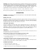
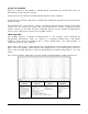
GAS PRESSURE REGULATOR INSTALLATION Gas regulator pressure is preset at 5” Water Column (W.C.) for natural gas, and 10” W.C. for propane gas. No further adjustment should be required. Install the regulator as close to the griddle on the gas supply line as possible. Make sure that the arrow on the underside of the regulator is oriented in the direction of gas flow to the griddle (Fig. 2) and the regulator is positioned with the vent plug and adjustment screw upright (Fig. 3). Fig. 2 Fig.
WARNING: APPLIANCES EQUIPPED WITH A FLEXIBLE ELECTRIC SUPPLY CORD ARE PROVIDED WITH A THREE-PRONG GROUNDING PLUG. IT IS IMPERATIVE THAT THIS PLUG BE CONNECTED INTO A PROPERLY GROUNDED THREE-PRONG RECEPTACLE. IF THE RECEPTACLE IS NOT THE PROPER GROUNDING TYPE, CONTACT AN ELECTRICIAN. DO NOT REMOVE THE GROUNDING PRONG FROM THIS PLUG. Power supply for electric thermostats is 120 volts, 5 amps, 50/60 Hertz, 1 phase. Do not connect the griddle to electrical supply until after gas connections are made.
USING THE GRIDDLE Each 12” section of the griddle is independently controlled by a thermostat. Turn the thermostat(s) to the desired setting. To preheat, turn the burners on about 20-25 minutes before cooking. A uniform and systematic approach to loading the griddle will produce the most consistent product results. The griddle plate is steel, but the surface is relatively soft and can be scored or dented by careless use of a spatula or scraper. Be careful not to dent, scratch, or gouge the plate surface.
CLEANING THE GRIDDLE WARNING: DISCONNECT THE ELECTRICAL POWER TO THE APPLIANCE AND FOLLOW LOCKOUT/TAGOUT PROCEDURES. Empty the grease drawer as needed throughout the day and regularly clean at least once daily. Clean the griddle regularly. A clean griddle always looks better, lasts longer and performs better. To produce evenly cooked, perfectly browned griddle products keep the griddle plate clean and free of carbonized grease.
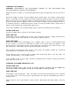
ADJUSTMENTS LEVELING 1. Place a level on the griddle. 2. Adjust legs by turning the bullet feet at the bottom of each leg. Using pliers or a crescent wrench, turn the feet counter-clockwise to increase height, and clockwise to decrease height until leveling is achieved. Do not extend the legs more than 1-¾”. CALIBRATION 1. Each thermostat controls a 12” zone of the griddle. Using a suitable temperature measurement device (i.e.
MAINTENANCE WARNING: THE GRIDDLE AND ITS PARTS ARE HOT. USE CARE WHEN OPERATING, CLEANING OR SERVICING THE GRIDDLE. WARNING: DISCONNECT THE ELETRICAL POWER TO THE APPLIANCE AND FOLLOW LOCKOUT/TAGOUT PROCEDURES. LUBRICATION All valves and thermostats must be checked and lubricated periodically. Check with your Service Agency for details. VENT Annually, when the griddle is cool, check the flue and clear any obstructions.
TROUBLESHOOTING PROBLEM POSSIBLE CAUSES Heat does not come on when the thermostat is turned on 1. 2. 3. 4. 5. 6. Not plugged in. Problem with thermostat. (Call for service) Circuit breaker tripped. Loose wiring connection. (Call for service) Pilot burner not lit. (Call for service) Problem with gas valve (Call for service) Pilot burner will not light 1. 2. 3. 4. Manual gas valve not turned on. Obstructed pilot orifice. (Call for service) Pilot gas turned off at automatic pilot.