
Griddle User Manual

-
9 -
This model features an electric ignition system that is controlled by a momentary power
switch. The power switch turns the electric ignition system off and on only and will only
supply power to the igniters when held down in the ON position. The burners and pilots
will continue to work with power switch in the OFF position until the gas supply to the unit
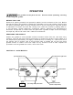
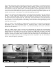
is cut off or the griddle gas shut-off valve is turned to the OFF position (Fig. 6). In the
event of a failure of the electronic ignition system, it is possible to ignite the pilots with an
outside source (such as a lit taper, etc). See pilot lighting procedure.
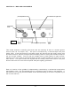
There is one pilot and one safety valve for every two burners except on the 36” and 60”
models. The 36” and 60” models have an odd number of main burners, therefore one of
the sets of pilots and safety valves in these models will control only one main burner.
The pilot burners are aligned with the pilot safety valve bush buttons. The pilot burners
are inset 12” from the front panel. The pilots are monitored by thermocouples and pilot
safety valves. If the pilot goes out, the safety valve will shut-off the gas supply to the
pilot and main burners.
Each 12” section of the griddle is independently controlled by a mechanical snap-action
thermostatic valve. The thermostats have an operating range of 200 to 550 degrees.
Once pilots are lit, turning the thermostats to the desired setting is all that is required to
put the unit into service.
Each 12” griddle section may be turned off independently by setting the corresponding
thermostat to the OFF position. You may also leave all thermostats set at the desired
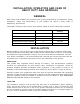
settings and turn all sections off at once by turning the griddle shut-off valve to the OFF
position (Fig. 6). This will turn off the gas supply to the pilots and thermostats for all
sections. Turning the griddle shut-off valve to the ON position(Fig. 5) and relighting the
pilots at the beginning of the next cooking shift will be required to put the unit back in
service. See pilot lighting procedure.
Fig. 6 Fig. 5
ON OFF