
Electric Steamer User Manual


MODEL C24EA - THERMOSTATS
F25213 (May 2006) Page 16 of 52
Installation
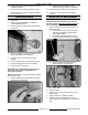
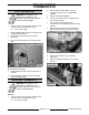
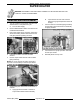
1. Insert capillary bulb through large compression
nut.
A. Route capillary bulb through top of heating
element.
B. Position capillary bulb between top of
second and third heating element coils.
Secure with hose clamp to second coil as
shown.
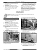
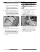
2. Apply pipe thread sealant to threads of large
capillary nut then install large compression nut.
A. Pull excess capillary tubing out of heating
element through large nut. Route capillary
tubing such that there are no sharp bends.
B. Tighten the small capillary compression nut
into the large compression nut.
NOTE: Install a new gasket when reassembling
steam generator tank. Temporarily secure gasket in
place with RTV109.
3. Reinstall remaining parts removed in reverse
order.
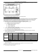
4. Torque heating element screws to 70 in*lb
following the heating element tightening
sequence as found under HEATING ELEMENT.
5. Check steamer for proper operation and leaks
around heating element gasket and high-limit
thermostat.
CONDENSATE THERMOSTAT
WARNING: DISCONNECT THE
ELECTRICAL POWER TO THE
MACHINE AND FOLLOW LOCKOUT /
TAGOUT PROCEDURES.
1. Turn off machine to drain steam generator tank.
Allow steamer to complete drain cycle.
A. Turn off water supply.
2. Remove LEFT SIDE PANEL as outlined in
COVERS AND PANELS.
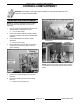
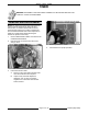
3. Disconnect electrical wiring to condensate
thermostat.
4. Remove condensate thermostat from drain box.
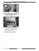
5. Reassemble parts removed in reverse order of
removal. Make certain to apply Loctite 565
thread sealant to threads of thermostat before
assembly.
6. Check steamer for proper operation and leaks
around condensate thermostat.