
Electric Steamer User Manual
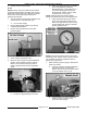
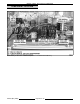
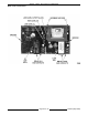

MODEL C24EA - SWITCHES, BUZZER AND SOLENOIDS
F25213 (May 2006) Page 32 of 52
C. Repeat clamping of steam outlet hose a
total of three times to find the average cut-
out pressure. Record pressure.
D. If pressure is outside tolerance (4.5 to 4.7
psi), adjustment is necessary. Refer to
Adjustment.
E. If cut-out pressure is within specifications,
shut off steamer. Allow time for steamer to
drain.
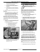
8. Remove test gauge and reinstall delime cap.
Adjustment
1. Allow full steam production to stabilize. This is
accomplished by allowing approximately five
cycles of fill to occur once steam is being
produced by the generator tank. Observe LED
on water control board to count cycles.
NOTE: Make small incremental adjustments (1/8
turn of toothed adjustment wheel) when adjusting
cut-out pressure. Wear a heat resistant glove when
working near hot surfaces such as when adjusting
pressure switch.
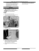
2. Referring to cut-out pressure recorded in Check
procedure, turn adjustment wheel to bring cut-
out pressure into tolerance.
A. From looking down on pressure switch:
1) Turn adjustment wheel CCW to
decrease cut-out pressure.
2) Turn adjustment wheel CW to
increase cut-out pressure.
B. Check cut-off pressure after making
adjustment. Repeat Check and Adjustment
as necessary until cut-out pressure is
within 4.5 to 4.7 psi.
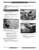
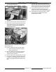
VACUUM RELIEF SOLENOID
WARNING: DISCONNECT THE
ELECTRICAL POWER TO THE
MACHINE AND FOLLOW LOCKOUT /
TAGOUT PROCEDURES.
NOTE: The vacuum relief solenoid on Professional
models is positioned with the solenoid coil toward the
cooking chamber away from the super heater. For
Basic models, the vacuum relief solenoid is
positioned with the coil toward the right side of
machine for easier serviceability.
1. Turn off machine to drain steam generator tank.
Allow steamer to complete drain cycle.
A. Turn off water supply.
2. Remove RIGHT SIDE COVER as outlined in
COVERS AND PANELS. Locate vacuum relief
solenoid on top of water level probe piping
assembly.
3. Disconnect hose from solenoid valve.
4. Disconnect electrical wiring to solenoid coil.
5. Remove retaining clip securing coil to valve
body then remove coil and wavy washer.
CAUTION: Do not force the super heater piping
assembly out of position to make clearance for
vacuum relief solenoid valve body removal.
Damage to generator tank weldment could occur.
NOTE: It may be necessary to turn the piping elbow
that connects the vacuum relief solenoid to the water
level piping assembly in order to clear the super
heater piping assembly when removing the valve
body.
6. Remove the valve body from piping assembly.
7. Reassemble parts removed in reverse order.
PROFESSIONAL MODEL SHOWN