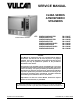
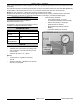
SERVICE MANUAL C24EA SERIES ATMOSPHERIC STEAMERS C24EA3 BASIC SHOWN C24EA3 208/240V PRO C24EA3 480V PRO C24EA5 208/240V PRO C24EA5 480V PRO C24EA3 208/240V BASIC C24EA3 480V BASIC C24EA5 208/240V BASIC C24EA5 480V BASIC ML-136037 ML-136044 ML-136038 ML-136047 ML-136043 ML-136045 ML-136046 ML-136048 - NOTICE This Manual is prepared for the use of trained Vulcan Service Technicians and should not be used by those not properly qualified.
MODEL C24EA - GENERAL TABLE OF CONTENTS GENERAL . . . . . . . . . . . . . . . . . . . . . . . . . . . . . . . . . . . . . . . . . . . . . . . . . . . . . . . . . . . . . . . . . . . . . . . . . . . . . . . . 3 COVERS AND PANELS . . . . . . . . . . . . . . . . . . . . . . . . . . . . . . . . . . . . . . . . . . . . . . . . . . . . . . . . . . . . . . . . . . . . . 6 DOOR . . . . . . . . . . . . . . . . . . . . . . . . . . . . . . . . . . . . . . . . . . . . . . . . . . . . . . . . . . . . . . . . . . . . .
MODEL C24EA - GENERAL GENERAL INTRODUCTION This manual is applicable to the models and ML numbers listed on the cover page. Procedures apply to all models unless specified otherwise. Steam Cooking Atmospheric steamers offer an efficient way to produce many foods in either small portions or larger batches.
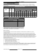
MODEL C24EA - GENERAL SPECIFICATIONS NOTE: All C24EA steamers, with exception of 480V steamers, are shipped pre-wired for 208/60/3 operation. Steamer heating element wiring connection change is required if connecting to 208/60/1, 240/60/1 or 240/60/3 electrical service. ELECTRICAL SPECIFICATIONS AMPERAGE MODEL TOTAL kW 3 PHASE Hz. 208V 1 PHASE 240V 480V L1 L2 L3 L1 L2 L3 L1 L2 L3 208V 240V C24EA3 - Basic 8.5 50/60 26.5 26.5 17.7 20.5 20.5 20.5 10.3 10.3 10.3 40.9 35.
MODEL C24EA - GENERAL Other chemical properties in water supplies can also affect good steam generation and vary from within each state and locality. The water level probes in the steam generator tank use ions in the water to detect the water level. Do not use fully demineralized or de-ionized water since it is non-conductive and the water level can not be detected. NOTE: The use of strainers, or filters will not remove minerals from the water.
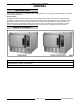
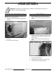
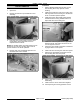
MODEL C24EA - COVERS AND PANELS COVERS AND PANELS WARNING: DISCONNECT THE ELECTRICAL POWER TO THE MACHINE AND FOLLOW LOCKOUT / TAGOUT PROCEDURES. RIGHT AND LEFT SIDE PANELS NOTE: Removal of left side panel is identical to the procedure for the right side panel. 1. TOP COVER 1. Remove RIGHT AND LEFT SIDE PANELS. 2. Remove the screws securing top cover to rear panel. 3. Remove the screws securing top cover to front panel. Screws are located on either side of the cooking cavity. 4.
MODEL C24EA - COVERS AND PANELS REAR PANEL WARNING: DISCONNECT THE ELECTRICAL POWER TO THE MACHINE AND FOLLOW LOCKOUT / TAGOUT PROCEDURES. 1. Remove screws securing top cover to rear panel and rear panel to steamer frame. SCREW LOCATION NOTE: If incoming plumbing or drain interferes with rear panel removal, turn off water supply and disconnect plumbing to machine. 2. Remove LEFT SIDE PANEL. 3. Disconnect vacuum relief hose from fitting. TOP COVER REMOVED FOR CLARITY 4.
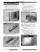
MODEL C24EA - DOOR DOOR WARNING: DISCONNECT THE ELECTRICAL POWER TO THE MACHINE AND FOLLOW LOCKOUT / TAGOUT PROCEDURES. REMOVAL GASKET 1. Close door. 1. Open door. 2. Remove LEFT SIDE PANEL as outlined in COVERS AND PANELS. 2. Remove the shoulder screws and pan pusher bracket from gasket plate. 3. Remove nuts from upper hinge located inside front panel. 4. Open door slightly, and while holding door, pull upper hinge away from front panel. 3. Remove gasket plate. 4.
MODEL C24EA - DOOR Installation DOOR HANDLE 1. Apply Lubriplate 630AA around slots of outer door housing where step spacers contact housing. 2. Install door handle into outer door housing such that hinge side of door housing is to the left and arrow on handle is pointed upward. 3. Install step spacer with smaller radius toward handle and door housing. Smaller radius is a slip fit with outer door housing slot. 4.
MODEL C24EA - DOOR Assembly LATCH ASSEMBLY 1. Apply Lubriplate 630AA to sides of sliding bracket. Separate outer door housing assembly from inner door panel as outlined under DOOR HANDLE. 2. Insert spring pin into bottom of sliding bracket. Remove screws securing latch assembly to inner door panel and remove latch mechanism. 3. Assemble sliding bracket into stationary bracket. 4.
MODEL C24EA - DOOR A. Press hinge bearing fully into door assembly using a C-clamp or equivalent. 2. Install outer door housing assembly as outlined in DOOR HANDLE. 3. Check opening and closing operation of door. 10. Reassemble parts removed in reverse order. 4. Check steamer for proper operation and leaks around door seal. 11. Check door for fit and proper door gasket sealing. HINGE BEARINGS DOOR LATCH ADJUSTMENT 1. Close door. 2. Remove LEFT SIDE PANEL as outlined in COVERS AND PANELS. 3.
MODEL C24EA - DRAIN BOX Adjustment 1. Reinstall striker with slot pointing upward and hand tighten nut only. 2. Close door to center striker in front panel mounting hole. 3. Open door and check striker slot for horizontal alignment. The slot on striker must be kept horizontal in order for door latch to catch properly and latch. 4. Once proper slot alignment has been set, hold striker close to its base then tighten the striker nut.
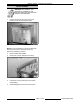
MODEL C24EA - COOKING COMPARTMENT COOKING COMPARTMENT WARNING: DISCONNECT THE ELECTRICAL POWER TO THE MACHINE AND FOLLOW LOCKOUT / TAGOUT PROCEDURES. REMOVAL AND REPLACEMENT NOTE: The cooking compartment and front panel are constructed as an assembly and cannot be separated. 1. Turn off machine to drain steam generator tank. Allow steamer to complete drain cycle. A. Turn off water supply. 2. Remove the RIGHT AND LEFT SIDE PANELS and TOP COVER as outlined in COVERS AND PANELS. 3.
MODEL C24EA - COOKING COMPARTMENT 8. Remove the screws securing front panel to lower louvered panel. 9. Remove the nuts securing rear of cooking compartment to the vertical mounting brackets (four places - located between cooking compartment and steam generator). 10. Remove cooking compartment assembly. 11. If removed or replacing cooking compartment, install insulation around cooking compartment. Secure insulation into position using high temperature aluminum foil tape. 12.
MODEL C24EA - THERMOSTATS THERMOSTATS HOLD THERMOSTAT WARNING: DISCONNECT THE ELECTRICAL POWER TO THE MACHINE AND FOLLOW LOCKOUT / TAGOUT PROCEDURES. 1. Turn off machine to drain steam generator tank. Allow steamer to complete drain cycle. A. 2. Remove RIGHT SIDE PANEL and TOP COVER as outlined under COVERS AND PANELS. 3. Remove HEATING ELEMENT. 4. Loosen hose clamp securing capillary bulb to top of heating element. 5.
MODEL C24EA - THERMOSTATS Installation 1. 2. CONDENSATE THERMOSTAT Insert capillary bulb through large compression nut. A. Route capillary bulb through top of heating element. B. Position capillary bulb between top of second and third heating element coils. Secure with hose clamp to second coil as shown. WARNING: DISCONNECT THE ELECTRICAL POWER TO THE MACHINE AND FOLLOW LOCKOUT / TAGOUT PROCEDURES. 1. Apply pipe thread sealant to threads of large capillary nut then install large compression nut. A.
MODEL C24EA - TIMER TIMER WARNING: DISCONNECT THE ELECTRICAL POWER TO THE MACHINE AND FOLLOW LOCKOUT / TAGOUT PROCEDURES. REMOVAL AND REPLACEMENT NOTE: The basic and professional model steamers use the same 60 minute timer. When the timer reaches zero, an external buzzer will sound and steam will stop entering the cooking compartment. The Professional steamer has extra components to utilize the constant steam setting allowing the steamer to operate continuously. 1.
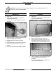
MODEL C24EA - HEATING ELEMENT HEATING ELEMENT WARNING: DISCONNECT THE ELECTRICAL POWER TO THE MACHINE AND FOLLOW LOCKOUT / TAGOUT PROCEDURES. REMOVAL AND REPLACEMENT 1. Turn off machine to drain steam generator tank. Allow steamer to complete drain cycle. A. Remove RIGHT SIDE PANEL and TOP COVER as outlined under COVERS AND PANELS. 3. Note heating element wire connection points then disconnect heating element lead wires from contactors. 7.
MODEL C24EA - HEATING ELEMENT 9. Reassemble parts removed in reverse order of removal. Tighten heating element screws evenly to 70 in*lbs. Follow tightening sequence pattern as shown in illustration. OVERHEAD VIEW OF HEATING ELEMENT 10. Check steamer for proper operation and leaks around heating element. DIAGNOSTIC CHECKS WARNING: CERTAIN PROCEDURES IN THIS SECTION REQUIRE ELECTRICAL TEST OR MEASUREMENTS WHILE POWER IS APPLIED TO THE MACHINE. EXERCISE EXTREME CAUTION AT ALL TIMES.
MODEL C24EA - SUPER HEATER SUPER HEATER WARNING: DISCONNECT THE ELECTRICAL POWER TO THE MACHINE AND FOLLOW LOCKOUT / TAGOUT PROCEDURES. B. REMOVAL AND REPLACEMENT 1. Turn off machine to drain steam generator tank. Allow steamer to complete drain cycle. A. 7. Check to make sure insulated piping assembly is horizontal or element head end of assembly is slightly elevated. 8. Check steamer for proper operation and leaks around super heater. 9. Reinstall panels and top cover. Turn off water supply.
MODEL C24EA - SUPER HEATER DIAGNOSTIC CHECKS WARNING: CERTAIN PROCEDURES IN THIS SECTION REQUIRE ELECTRICAL TEST OR MEASUREMENTS WHILE POWER IS APPLIED TO THE MACHINE. EXERCISE EXTREME CAUTION AT ALL TIMES. IF TEST POINTS ARE NOT EASILY ACCESSIBLE, DISCONNECT POWER AND FOLLOW LOCKOUT / TAGOUT PROCEDURES, ATTACH TEST EQUIPMENT AND REAPPLY POWER TO TEST. 1. 2. 3. Check voltage across super heater wires at limiting and regulating contactor terminals. A. If voltage is correct, check current draw (step 2).
MODEL C24EA - WATER LEVEL CONTROL COMPONENTS WATER LEVEL CONTROL COMPONENTS WATER LEVEL CONTROLS Low Level Cut-Off & Differential Control The steamer is equipped with three water level sensing probes (high, low and low level cut-off) and a water level control board. The water level control board performs two functions: 1) Provide low level cut-off protection to shut off the heat source in case the water level drops below the low level cut-off (LLCO) probe.
MODEL C24EA - WATER LEVEL CONTROL COMPONENTS WATER LEVEL CONTROL BOARD WATER LEVEL PROBES WARNING: DISCONNECT THE ELECTRICAL POWER TO THE MACHINE AND FOLLOW LOCKOUT / TAGOUT PROCEDURES. WARNING: DISCONNECT THE ELECTRICAL POWER TO THE MACHINE AND FOLLOW LOCKOUT / TAGOUT PROCEDURES. CAUTION: Certain components in this system are subject to damage by electrostatic discharge during field repairs. A field service grounding kit is available to prevent damage.
MODEL C24EA - WATER LEVEL CONTROL COMPONENTS DUAL WATER VALVE FLOW RATES Flow Rate (GPM) Machine Valve Type Fast Flow Slow Flow Type Valve Valve Fill (Filtered 3 & 5 Pan 4.8 0.15 Water) Condensate 3 - Pan 4.8 0.75 (Non-Filtered 5 - Pan 4.8 1.35 Water) Filtered Water Solenoid Valve 1. NOTE: Perform a steam generator tank cleaning as outlined under STEAM GENERATOR TANK CLEANING. FILTERED AND NON-FILTERED WATER SOLENOID VALVES Turn off machine to drain steam generator tank.
MODEL C24EA - WATER LEVEL CONTROL COMPONENTS 6. Reassemble parts removed in reverse order of removal. 7. Verify that the filtered water supply is connected to the input of the filtered water solenoid valve. 8. Check steamer for leaks and proper operation. MANUAL DRAIN VALVE (BASIC) WARNING: DISCONNECT THE ELECTRICAL POWER TO THE MACHINE AND FOLLOW LOCKOUT / TAGOUT PROCEDURES. Non-Filtered Cold Water Solenoid Valve 1. Turn off machine to drain steam generator tank.
MODEL C24EA - WATER LEVEL CONTROL COMPONENTS NOTE: Apply pipe thread sealant to plumbing threads before assembly. 7. Reassemble parts removed in reverse order of removal. 8. For Basic model steamers, perform ON/OFF SWITCH ADJUSTMENT as outlined in ON/OFF SWITCH. 9. Check steamer for leaks and proper operation. A. Rotate knob CW to manually open the drain valve. Turning knob such that the slot in knob is in a vertical orientation indicates the drain valve is open.
MODEL C24EA - WATER LEVEL CONTROL COMPONENTS 5. Disconnect the drain and drain flush hoses from the Tee located below the drain valve. 6. Remove the drain valve body from the steam generator tank. 7. Separate the Tee and nipple from the drain valve body. 8. Reassemble parts removed in reverse order. Apply liquid pipe thread sealant to threads of plumbing connections.
MODEL C24EA - SWITCHES, BUZZER AND SOLENOIDS SWITCHES, BUZZER AND SOLENOIDS ON/OFF SWITCH WARNING: DISCONNECT THE ELECTRICAL POWER TO THE MACHINE AND FOLLOW LOCKOUT / TAGOUT PROCEDURES. Basic Models 1. Pull out on handle to turn steamer off and drain generator tank. 2. Remove the RIGHT SIDE PANEL. 3. Locate the on/off switch assembly mounted to the manual drain valve. 4. Note wiring locations and disconnect electrical wiring from switch. 5. Remove switch from switch mounting bracket.
MODEL C24EA - SWITCHES, BUZZER AND SOLENOIDS 3. Push handle fully in and keep in position. 3. Disconnect electrical plug from switch. 4. Position plunger of on/off switch against linkage bracket such that plunger is fully engaged. 4. Remove switch from front panel. 5. Reassemble parts removed in reverse order. DOOR SWITCH WARNING: DISCONNECT THE ELECTRICAL POWER TO THE MACHINE AND FOLLOW LOCKOUT / TAGOUT PROCEDURES. Removal A. B. 1. Remove the RIGHT SIDE PANEL. 2.
MODEL C24EA - SWITCHES, BUZZER AND SOLENOIDS 3. A. Close door. B. Push switch up against switch linkage as far as possible. C. Tighten switch mounting hardware. Check door switch operation. A. Set meter to measure resistance and place meter leads across the COMMON and NORM OPEN terminals of switch. With door closed, meter should indicate a closed circuit. B. Open door. Meter should indicate an open circuit as door is opened. 4. Check steamer for proper operation. 5.
MODEL C24EA - SWITCHES, BUZZER AND SOLENOIDS 6. Perform pressure switch Check. B. Check NOTE: Pressure can be checked with the small air pocket that exists between the delime port cap and water level probe housing in the delime hose. Make certain that no leaks exist in generator tank or pressure gauge fittings. 1. NOTE: Operating pressures will vary slightly between machine being serviced and gauge used. Turn off machine to drain steam generator tank. Allow steamer to complete drain cycle. A. C.
MODEL C24EA - SWITCHES, BUZZER AND SOLENOIDS 8. C. Repeat clamping of steam outlet hose a total of three times to find the average cutout pressure. Record pressure. D. If pressure is outside tolerance (4.5 to 4.7 psi), adjustment is necessary. Refer to Adjustment. E. If cut-out pressure is within specifications, shut off steamer. Allow time for steamer to drain. Remove test gauge and reinstall delime cap. Adjustment 1. Allow full steam production to stabilize.
MODEL C24EA - SWITCHES, BUZZER AND SOLENOIDS A. Install valve with the inlet (ON) side of valve connected to the back panel port and the outlet (OFF) side of valve connected to the water level control plumbing. Apply liquid thread sealant to threads of piping before assembly. 7. Reassemble parts removed in reverse order. Perform DOOR LATCH ADJUSTMENT as outlined under DOOR. BUZZER WARNING: DISCONNECT THE ELECTRICAL POWER TO THE MACHINE AND FOLLOW LOCKOUT / TAGOUT PROCEDURES. 1.
MODEL C24EA - STEAM GENERATOR TANK STEAM GENERATOR TANK WARNING: DISCONNECT THE ELECTRICAL POWER TO THE MACHINE AND FOLLOW LOCKOUT / TAGOUT PROCEDURES. REMOVAL AND REPLACEMENT 1. Turn off machine to drain steam generator tank. Allow steamer to complete drain cycle. A. Turn off water supply. 2. Remove the TOP COVER, RIGHT and REAR PANEL as outlined under COVERS AND PANELS. 3. Disconnect electrical wiring then remove HOLD THERMOSTAT. 4. Disconnect the fill union fitting. 7.
MODEL C24EA - STEAM GENERATOR TANK 10. Remove remaining steam outlet elbow plumbing from steam generator tank. 18. Reinstall parts removed in reverse order of removal. Apply liquid thread sealant to all pipe threads connected to the steam generator tank. Do not apply thread sealant to fill union fitting. 19. Torque heating element screws to 70 in*lb following the heating element tightening sequence as found under HEATING ELEMENT. 20. Check steamer for proper operation.
MODEL C24EA - ELECTRICAL OPERATION ELECTRICAL OPERATION COMPONENT FUNCTION Water Level Control (WLC) Board . . . . . . . . . Controls water level by monitoring conditions of the three water level probes H, L and LLCO. Buzzer . . . . . . . . . . . . . . . . . . . . . . . . . . . . . . . . Creates audible signal when timed cook cycle is complete. Contactor, Limiting . . . . . . . . . . . . . . . . . . . . . Connects one side of heating elements to incoming power.
MODEL C24EA - ELECTRICAL OPERATION Solenoid (4SOL), Slow Fill . . . . . . . . . . . . . . . Primary fill for Basic machines and secondary fill for Professional machines. Energized as necessary during operation to replenish water in generator tank. Solenoid (5SOL), Vacuum Relief . . . . . . . . . . . Provides open air line for vacuum relief during drain cycle to prevent cooking chamber flex. Switch (1S), Power . . . . . . . . . . . . . . . . . . . . .
MODEL C24EA - ELECTRICAL OPERATION COMPONENT LOCATION Electrical Control Panel NOTE: Relay K4 and transformer T2 are present on Professional models only.
MODEL C24EA - ELECTRICAL OPERATION Water Level Control Board Page 39 of 52 F25213 (May 2006)
MODEL C24EA - ELECTRICAL OPERATION Front Panel F25213 (May 2006) Page 40 of 52
MODEL C24EA - ELECTRICAL OPERATION Steam Generator and Back Panel Page 41 of 52 F25213 (May 2006)
MODEL C24EA - ELECTRICAL OPERATION A. Internal latching relay (ILR) coil on WLC board energizes. Refer to the correct wiring diagram for model being serviced when reviewing sequence of operation. B. High level (HL) coil de-energized by ILR-2 contacts opening. NOTE: If power switch is set to off when service voltage is applied, steamer will enter the timed drain cycle. C. Slow fill solenoid de-energized by opening of HL contacts on WLC board. SEQUENCE OF OPERATION Basic Model 1. Conditions A.
MODEL C24EA - ELECTRICAL OPERATION B. C. Time delay relay is energized through terminals 2 & 3 for set time (90 seconds). Output (120VAC) on terminal 1. E. Time delay relay output energizes K3 coil. 1) X1 potential to L1 of WLC board through N.O. contacts K3-5/3 2) LLCO relay K2 coil energized through closed N.O. contacts K3-5/3, WLC board N.O. contacts LLCO and N.O. contacts K3-6/4. a. 3) Drain Flush Solenoid enabled by closure of N.O. contacts K2-3/5. 2.
MODEL C24EA - ELECTRICAL OPERATION A. 8. 9. No action as internal latching relay (ILR-1) contacts are open. C. Water level reaches high level(H) probe. A. Internal latching relay (ILR) coil on WLC board energizes. B. High level (HL) coil de-energized by ILR-2 contacts opening. C. Slow Fill Solenoid de-energized by opening of HL contacts on WLC board. D. HL LED on WLC board turns off. D. Timer knob set to CONSTANT for continuous steam operation or Timer knob is turned to a timed setting. A.
MODEL C24EA - ELECTRICAL OPERATION WIRING DIAGRAMS Heating Element Wiring Page 45 of 52 F25213 (May 2006)
MODEL C24EA - ELECTRICAL OPERATION F25213 (May 2006) Page 46 of 52
MODEL C24EA - ELECTRICAL OPERATION Page 47 of 52 F25213 (May 2006)
MODEL C24EA - ELECTRICAL OPERATION F25213 (May 2006) Page 48 of 52
MODEL C24EA - ELECTRICAL OPERATION Page 49 of 52 F25213 (May 2006)
MODEL C24EA - TROUBLESHOOTING TROUBLESHOOTING SYMPTOM Compartment leaks water around door. Steamer leaks water. POSSIBLE CAUSES Unit not level. Drain line obstructed or not to an open gap drain. Door gasket damaged. Solenoid (2SOL) inoperative or plugged. Lack of water supply. Drain water thermostat stuck open. Drain cold water condensate valve malfunction. Worn gasket - See DOOR section. Damaged gasket. Drain line obstructed or not to an open drain.
MODEL C24EA - TROUBLESHOOTING -NOTES- Page 51 of 52 F25213 (May 2006)
MODEL C24EA - CONDENSED SPARE PARTS LIST CONDENSED SPARE PARTS LIST C24EA PART NO.