
Electric Steamer User Manual
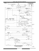

MODEL C24EA - ELECTRICAL OPERATION
F25213 (May 2006) Page 44 of 52
A. No action as internal latching relay (ILR-1)
contacts are open.
8. Water level reaches high level(H) probe.
A. Internal latching relay (ILR) coil on WLC
board energizes.
B. High level (HL) coil de-energized by ILR-2
contacts opening.
C. Slow Fill Solenoid de-energized by opening
of HL contacts on WLC board.
D. HL LED on WLC board turns off.
9. Timer knob set to CONSTANT for continuous
steam operation or Timer knob is turned to a
timed setting.
A. Power (120VAC) present to Door Switch
wire #19.
B. If Timer is set to a timed setting, Timer
motor is energized through closure of N.O.
contacts K1-6/4. Count down time begins.
10. Steamer door is closed.
A. Door Switch (2S) contacts close. Cook light
(2LT - Red) illuminates.
B. Regulating contactor remains energized as
long as door is closed and Timer is set to
CONSTANT or time remains on timed
cycle.
11. Temperature of condensate exiting cooking
cavity increases to above 135EF.
A. Condensate thermostat closes energizing
cooling solenoid 1SOL. Condensate is
cooled in drain box before entering facility
drain system.
12. Door opened during timed cook cycle.
A. Timer continues count down until time
equals zero even if steamer door is
opened.
B. Regulating contactor de-energizes and
cook light turns off.
13. Time reaches zero.
A. Buzzer is energized through N.O. contacts
K1-6/4 and Timer - 11/14.
1) Buzzer remains energized until timer
knob is turned to OFF, new time or
CONSTANT is selected or steamer is
turned off.
14. Power Switch (1S) pushed to off.
A. Power (3LT), Cook (2LT) and Ready (1LT)
lights turn off.
B. Time delay relay is energized through
terminals 2 & 3. Output (120VAC) on
terminal 1 for 90 seconds.
C. Time delay relay output energizes K3 coil.
1) X1 potential to L1 of WLC board
through N.O. contacts K3-3/5.
2) Relay K2 coil energized through WLC
N.O. contacts LLCO and N.O.
contacts K3-6/4.
3) Heating element and timer control
circuits are disabled by opening of
N.C. contacts K3-6/2.
D. Power (120VAC) across primary of drain
transformer. Motorized drain valve
energized. Drain valve opens and tank
begins to drain.
1) Drain valve N.O. contacts close.
15. Condensate Thermostat reaches 135EF,
contacts close. Drain water temperature is
regulated through condensate thermostat.
A. Cooling Solenoid (1SOL) energized
through closure of Condensate Thermostat
contacts.
B. Flush Solenoid (2SOL) energized through
closure of N.O. contacts K2-3/5 and drain
valve N.O. contacts.
16. Tank water level drops below L probe.
A. Internal latching relay (ILR) de-energizes.
1) High level coil (HL) energized on WLC
board. HL LED on WLC board lights.
17. Tank water level drops below LLCO probe.
A. Relay K2 de-energized through opening of
WLC board LLCO N.O. contacts.
B. Vacuum Relief Solenoid energized through
N.C. contacts K2-2/6.
C. Fast Fill Solenoid energized through WLC
(LLCO) N.C. contacts and N.C. contacts
K2-5/1.
D. Flush Solenoid (2SOL) remains energized
through WLC (LLCO) N.C. contacts.
18. Time Delay Relay time elapses.
A. Power (120VAC) removed from output of
Time Delay Relay terminal 1.
1) All Solenoids, coils and WLC board
are de-energized.
2) Motorized drain valve de-energized.
Drain valve closes.