
Service manual

F35425 (February 2006) Page 30 of 40
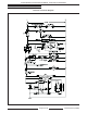
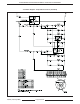
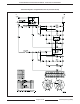
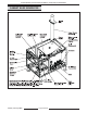
C24GA SERIES CONVECTION STEAMERS - ELECTRICAL OPERATION
Hold Thermostat........................... The Hold Thermostat energizes the Generator Slow Fill Solenoid Valve when
generator temperature reaches the non-adjustable setpoint at 190°F.
Drain.............................................The Drain is located on the lower right of the base and removes steam conden-
sate and water from cooking compartments and generator.
Metal Fiber Main Burner............... The Metal Fiber Main Burner is accessible from the front. This burner heats the
water in the generator to generate steam.
Gas Combination Control Valve....The Gas Combination Control Valve is part of the Burner Assembly and is a
gas solenoid that opens to allow gas flow when a call for heat is made and that
also regulates the manifold gas pressure.
Blower Motor................................ The Blower Motor is part of the Burner Assembly and provides airflow for the
metal fiber burner. The blower is accessible through the front of the base.
Blower Air Pressure Switch.......... The Blower Air Pressure Switch is part of the Burner Assembly and closes at
0.4" W.C. to apply operating voltage to the ignition module.
Gas Orifice....................................The Gas Orifice is part of the Blower Assembly and controls the flow of gas to
the burner.
Ignition Control Module................ The Ignition Control Module controls the ignition of the gas pilot and main
burner.
24 VAC Transformer.......................The 24 VAC Transformer reduces the input 120 VAC to the 24 VAC required by
the Ignition Module.
Super Heater Assembly.................The Super Heater Assembly (Heat Exchanger) is located at the rear of the
base surrounding the flue and is used to raise the temperature of the steam by
passing the steam around the flue assembly.
Drain Valve Timer......................... The Drain Valve Timer turns on for 1000 seconds when Power On/Off Switch
is set to off position to operate the Drain Solenoid.
5 PSI Pressure Relief Valve.......... The 5 psi Pressure Relief Valve opens if the generator pressure exceeds 5 psi
to prevent further pressure rise.