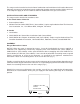
INSTALLATION & OPERATION MANUAL EG SERIES GAS RANGES MODEL EG24 EG36 EG48 EG60 EG160 EG260 ML-52486 ML-52487 ML-114956 ML-52488 ML-52489 ML-52490 MODEL EG36 VULCAN-HART COMPANY, FORM 31053 Rev. A (4-98) P.O. BOX 696, LOUISVILLE, KY 40201-0696, TEL.
IMPORTANT FOR YOUR SAFETY THIS MANUAL HAS BEEN PREPARED FOR PERSONNEL QUALIFIED TO INSTALL GAS EQUIPMENT, WHO SHOULD PERFORM THE INITIAL FIELD START-UP AND ADJUSTMENTS OF THE EQUIPMENT COVERED BY THIS MANUAL. POST IN A PROMINENT LOCATION THE INSTRUCTIONS TO BE FOLLOWED IN THE EVENT THE SMELL OF GAS IS DETECTED. THIS INFORMATION CAN BE OBTAINED FROM THE LOCAL GAS SUPPLIER.
TABLE OF CONTENTS EG SERIES GAS RANGE MODELS . . . . . . . . . . . . . . . . . . . . . . . . . . . . . . . . . . . . . . . . . . . . . . . . 4 GENERAL. . . . . . . . . . . . . . . . . . . . . . . . . . . . . . . . . . . . . . . . . . . . . . . . . . . . . . . . . . . . . . . . . . . . . . 5 INSTALLATION . . . . . . . . . . . . . . . . . . . . . . . . . . . . . . . . . . . . . . . . . . . . . . . . . . . . . . . . . . . . . . . . . 5 Unpacking . . . . . . . . . . . . . . . . . . . . . . . . . . . . . . . . .
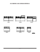
EG SERIES GAS RANGE MODELS EG60 EG36 EG160 EG260 EG48 EG24 PL-53006 —4—
Installation, Operation and Care of MODEL EG SERIES GAS RANGES KEEP THIS MANUAL FOR FUTURE REFERENCE GENERAL Vulcan ranges are produced with quality workmanship and material. Proper installation, usage and maintenance of your range will result in many years of satisfactory performance. Vulcan suggests that you thoroughly read this entire manual and carefully follow all of the instructions provided. Standard equipment includes 1 oven rack.
The range must be installed so that the flow of combustion and ventilation air will not be obstructed. Adequate clearance for air openings into the combustion chamber must be provided. Make sure there is an adequate supply of air in the room to allow for combustion of the gas at the burners. INSTALLATION CODES AND STANDARDS The range must be installed in accordance with: In the United States of America 1. State and local codes. 2. National Fuel Gas Code, ANSI-Z223-1 (latest edition).
Installation of Broiler/Griddle Bricks The broiler/griddle utilizes ceramic fire bricks for heat radiation of the burners. Install the broiler bricks before connecting the gas supply line. 1. Remove the six 51⁄4" x 21⁄4" (133.3 x 57 mm) and six 51⁄4" x 51⁄16" (133.3 x 128.6 mm) bricks from the shipping box. 2. Install the six 51⁄4" x 21⁄4" (133.3 x 57 mm) bricks to the left- and right-hand sides of the burner. To install the bricks, insert them one at a time through the opening in the front of the broiler.
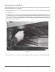
Installation of Griddle Top Bricks The griddle top section is extremely heavy. It will require three people to install the griddle and griddle brick — two people to lift the griddle plate (Fig. 3) and one person to set the bricks and griddle thermostat capillary bulb(s) in place. Fig. 3 The griddle top section utilizes a two-fold baffle assembly to support the composite/mortar fire bricks. There will always be only one small 61⁄2" (165 mm) wide baffle assembly with every griddle top order.
4. Exercise caution when placing brick in a thermostatically controlled griddle section. DO NOT hit thermostat bulb while installing bricks. The thermostat bulb is a sensitive device and may be easily knocked out of adjustment. Into the 61⁄2" (165 mm) wide baffle, install: a. Two 10" x 4" (254 x 101.6 mm) bricks, placing the miter edge, one to each side of the front burner baffle area (Fig. 4). b. Two 7" x 4" (177.8 x 101.6 mm) bricks, one to each side of the rear burner baffle area (Fig. 4). c.
Installation of Hot Top Bricks The hot top sections utilize composite/mortar fire bricks for heat distribution of the burners. Install these bricks before connecting the gas supply line or installing the back riser. 1. The composite/mortar bricks are shipped in a rectangular cardboard box. Locate box and carefully remove two 10" x 4" (254 x 101.6 mm), two 7" x 4" (177.8 x 101.6 mm), and one triangular 97⁄16" x 2" x 17⁄8" (239.7 x 50.8 x 47.6 mm) bricks.
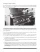
Fig. 5 Fig. 6 3. Assemble the required components as shown in Fig's. 5 and 6. 4. Lift the assembly up, sliding the channels into the space provided at the rear of the range (this may require two people). 5. It may be necessary to pull the heat shield bottom out slightly in order to clear the oven flue box area. Be sure the backsplash is resting evenly and the channel holes are lining up with the holes provided in the right- and left-hand body side (Fig's. 7 & 8). Fig. 7 Fig.
6. Install eight #10 sheet metal screws (4 to each channel leg) (Fig. 9). Fig. 9 7. From the front, install four 1⁄4-20 x 25⁄16" (58.7 mm) long machine screws and secure bolts with locknuts. Do not tighten the screws all the way down. Leave about 1⁄4" (6.4 mm) of play in each screw (Fig. 10) 8. Lift the shelf up and slide the shelf into position over the screw heads (Fig. 11). 9. Tighten the four screws to secure the shelf. Fig. 11 Fig.
LEVELING Check the leveling of the range. Place a carpenter's level inside the oven cavity across the oven rack(s). Level front-to-back and side-to-side. To adjust the leveling, tilt the range to one side, and using channel locks, unscrew the adjustable leg insert as required. Repeat this procedure as necessary for each leg. Casters for this range are of the non-adjustable type. Therefore, the floor must be level. If floor surface is not level, the range will experience cooking problems.
Fig. 12 A leak limiter is supplied with every regulator to allow excess gas pressure to escape. Do not obstruct leak limiter on gas pressure regulator, as obstruction may cause regulator to malfunction. WARNING: PRIOR TO LIGHTING, CHECK ALL JOINTS IN THE GAS SUPPLY LINE FOR LEAKS. USE SOAP AND WATER SOLUTION. DO NOT USE AN OPEN FLAME. After piping has been checked for leaks, all piping receiving gas should be fully purged to remove air.
OPERATION WARNING: THE RANGE AND ITS PARTS ARE HOT. BE VERY CAREFUL WHEN OPERATING, CLEANING OR SERVICING THE RANGE. CONTROLS THERMOSTAT DIAL — Allows operator to regulate oven temperature from low to 500°F (260°C). OPEN TOP BURNER KNOB — Regulates gas flow to top burners. To increase heat, turn knob counterclockwise; to decrease heat, turn knob clockwise. GRIDDLE BURNER KNOB — Regulates gas flow to the griddle or hot top burner.
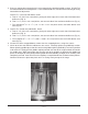
Open Top Burners 1. Turn main gas supply ON. 2. Wait 30 seconds and, using a taper, light the open top pilot (Fig. 14). Fig. 14 3. If pilot fails to light, turn main gas supply OFF. Wait 5 minutes and repeat the above procedures. 4. Turn one open top burner valve ON to remove air from the gas line. Turn burner valve OFF when gas begins to flow. Nightly Shutdown: Turn burner valve OFF; pilot will remain lit. Complete Shutdown: Turn burner valve OFF; pilot will remain lit. Turn main gas supply OFF.
1. Open kick panel (Fig. 15) and lift up the pilot lighting hole cover. 2. Light pilot by depressing the reset button located behind the kick panel (Fig. 16). Continue to hold reset button in for 1 minute. If pilot fails to light, turn main gas supply OFF and wait 5 minutes before repeating Step 2. Fig. 15 Fig. 16 3. After pilot is lit, turn the thermostat to the desired setting. Nightly Shutdown: Turn oven thermostat OFF. Complete Shutdown: Turn oven thermostat OFF. Turn main gas supply OFF.
RACK ARRANGEMENT Capacity The oven has two rack positions and is supplied with one oven rack. Additional racks may be obtained through a Vulcan-Hart parts depot. For best results when baking cakes and pastries, it is recommended that only a single rack position be utilized. However, proper rack usage and positioning is really determined by the individual cooking needs of the operator. If you are cooking a large roast, the entire oven cavity may be utilized.
PREHEATING Oven Turn thermostat control to the desired cooking temperature and preheat oven for 25 minutes. To save on gas consumption, do not operate oven at maximum heat when it is not necessary. Turn thermostat down to 250°F (121°C) or OFF when oven is not in use or during idle cooking periods. Hot Top Burners Turn burner ON to highest heat to heat hot top section quickly. Hot top will be ready to cook on in about 10 minutes.
COOKING CHART Recommended temperatures and times are intended as a guide only. Adjustments must be made to compensate for elevation, variations in recipes, ingredients, preparation and personal preference on product appearance. Meat roasting is most satisfactory at temperatures of 225°F to 325°F (107°C to 162.7°C) for beef, lamb, poultry and ham, and 325°F (162.7°C) for fresh pork as recommended by USDA and American Meat Institute. A pan, approximately 12" x 20" x 1" (304.8 x 508 x 25.
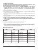
RECOMMENDED TEMPERATURES AND TIMES FOR BAKING - Cont'd. PRODUCT TEMPERATURE APPROX. TIME (MIN.) 300 to 325°F/148.9 to 162.8°C 15 to 20 315 to 340°F/157.2 to 171°C 20 to 30 Cup Cakes 350 to 400°F/176.7 to 204.4°C 6 to 12 Frozen Fruit Pies 350 to 375°F/176.7 to 190.5°C 30 to 45 Pumpkin or Custard Pies 300 to 350°F/148.9 to 176.6°C 30 to 45 350 to 400°F/176.7 to 204.4°C 30 to 45 Meringue Pies 350 to 425°F/176.7 to 218.3°C 6 to 10 Fruit Turnovers Sheet pans 350 to 375°F/176.7 to 190.
OVEN BROILING OR FRYING PRODUCT TEMPERATURE APPROX. TIME (MIN.) Hamburger Patties 8 per lb.(0.5 kg) - Med. well done 6 per lb. (0.5 kg) 4 per lb. (0.5 kg) 400 to 450°F/204.4 to 232.2°C 400 to 450°F/204.4 to 232.2°C 375 to 385°F/190.5 to 196°C 5 to 6 7 to 10 8 to 12 Fish Sticks & Portions Frozen bread. - 1 oz. (28.3 grams) 21⁄2 to 3 oz. (70.8 to 85 grams) 350 to 400°F/176.7 to 204.4°C 350 to 375°F/176.7 to 190.5°C 6 to 10 8 to 15 Chicken Pieces Broiled or Oven Fried 2 to 21⁄2 lbs. (0.9 to 1.
CLEANING Do not use Dawn dish detergent to clean the exterior or interior components of the range. DO NOT use scouring powder. It is extremely difficult to remove completely, and accumulations can build up that will damage the oven. Vulcan painted surfaces may be cleaned using a soft cloth and mild detergent solution. RANGES Daily: Remove nickel-plated racks and clean in a sink. While still warm, wipe top with a soft cloth or other grease absorbing material to remove spillovers, grease, etc.
Oven Door Gasket To clean the oven door gasket, use a soft cloth or sponge and a mild cleanser. DO NOT USE STRONG OVEN CLEANERS SUCH AS EASY OFF® OR MR. MUSCLE®. Cleaners of this nature will destroy the gasket material. GRIDDLE PLATE Cleaning the griddle section will produce evenly cooked, perfectly browned griddle products and will keep the cooking surface free from carbonized grease. Carbonized grease on the surface hinders the transfer of heat to the food.