SERVICE MANUAL ONE POWERFUL PACKAGE V SERIES HDR GAS RANGES TOPS Open Top Hot Top Griddle Top Work Surface BASES Standard Oven Convection Oven Cabinet Base - NOTICE This manual is prepared for use by trained service technicians and should not be used by those not properly qualified. If you have attended a service school for this product, you may still be qualified to perform the procedures described in this manual. This manual is not intended to be all encompassing.
IMPORTANT FOR YOUR SAFETY THIS MANUAL HAS BEEN PREPARED FOR PERSONNEL QUALIFIED TO INSTALL GAS EQUIPMENT, WHO SHOULD PERFORM THE INITIAL FIELD START-UP AND ADJUSTMENTS OF THE EQUIPMENT COVERED BY THIS MANUAL. POST IN A PROMINENT LOCATION THE INSTRUCTIONS TO BE FOLLOWED IN THE EVENT THE SMELL OF GAS IS DETECTED. THIS INFORMATION CAN BE OBTAINED FROM THE LOCAL GAS SUPPLIER. IN THE EVENT OF A POWER FAILURE, DO NOT ATTEMPT TO OPERATE THIS DEVICE.
TABLE OF CONTENTS GENERAL Introduction Installation Operation Cleaning Lubrication Tools Specifications REMOVAL AND REPLACEMENT OF PARTS Electrical Lockout / Tagout Procedure Gas Lockout / Tagout Procedure Units Mounted On Casters Covers and Panels Manifold Cover Kick Panel Component Removal Oven Control Panel(S Model) Oven Control Panel (C Model) Pilot Safety Valve and temperature Control Assembly (S Model) Pilot Safety Valve (S Model) Temperature Control (S Model) Temperature Control (C Model) Solenoid, P
Top Burner Adjustment Oven Burner Adjustment Oven Door Microswitch Test Fan Control Switch Test (C Model) Convection Oven Motor Test (C Model) Solenoid Test (C Model) ELECTRICAL OPERATION Component Function Sequence of Operation Wiring Diagrams 120V C Model 208V C Model TROUBLESHOOTING Troubleshooting Chart CONDENSED SPARE PARTS LIST Page 4 of 36
GENERAL INTRODUCTION Procedures in this manual will apply to all models unless specified. Pictures and illustrations can be of any model unless the picture or illustration needs to be model-specific. Before performing maintenance on the equipment, thoroughly read this manual and carefully follow the instructions in the order given. Installation Refer to the Installation and Operation manual for detailed installation instructions.
Gas Line Pressures Operating Pressures Natural - Recommended (in. W.C.) 6.0 Propane - Recommended (in. W.C.) 10.0 Incoming Pressure Natural - Recommended (in. W.C.) 7.0 min. Propane - Recommended (in. W.C.) 11.0 min REMOVAL AND REPLACEMENT OF PARTS ELECTRICAL LOCKOUT/TAGOUT Electrical Lockout/Tagout procedures are used to protect personnel working on an electrical appliance. Perform the following steps when performing any type of maintenance or service on an electrically operated appliance.
GAS LOCKOUT/TAGOUT The Gas Lockout/Tagout procedure is used to protect personnel working on a gas appliance. Before performing any maintenance or service that requires gas disconnections, follow these steps: WARNING: All gas joints disturbed during servicing must be checked for leaks. Do not use an open flame. Use a hazardous gas tester or a soap and water solution (Bubbles indicate a gas leak). Failure to comply can cause property damage, injury or death.
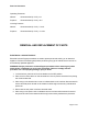
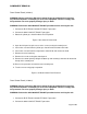
WARNING: Perform the GAS LOCKOUT/TAGOUT procedure before servicing the unit. 1. Perform the ELECTRICAL LOCKOUT/TAGOUT Procedure. 2. Rotate the yellow gas shut-off knob to the OFF position. Figure 1: Gas Shut-Off Valve Knob 3. Loosen the setscrew in the burner control knobs and remove the knobs. 4. Remove the two (2) drive screws securing the manifold cover in place and remove the manifold cover. 5. Reverse the procedure to install the manifold cover.
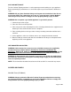
COMPONENT REMOVAL Oven Control Panel (S Model) WARNING: Always perform the Electrical Lockout/Tagout procedure before removing any sheet metal panels or attempting to service this equipment. Failure to comply with this procedure can cause property damage, injury or death. WARNING: Perform the GAS LOCKOUT/TAGOUT procedure before servicing the unit. 1. Perform the ELECTRICAL LOCKOUT/TAGOUT procedure. 2. Perform the GAS LOCKOUT/TAGOUT procedure. 3. Rotate the yellow gas shut-off knob to the OFF position.
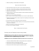
3. Rotate the yellow gas shut-off knob to the OFF position. Figure 6: Gas Shut-Off Valve Knob 4. Open the kick panel to gain access to the screw securing the control panel. 5. Loosen the setscrew from the yellow gas shut-off knob and remove the knob. 6. Loosen the setscrew from the temperature control knob and remove the knob. 7. Remove the oven knob ring. 8. Remove the two (2) screws from the temperature control mount bracket located in the front of the control panel. 9.
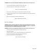
5. Tag and disconnect the electrical connectors to the temperature control. 6. Remove the screws securing the gas mount bracket to the oven. 7. Remove the gas mount bracket, pilot safety valve and temperature control assembly from the oven. WARNING: All gas joints disturbed during servicing must be checked for leaks. Do not use an open flame. Use a hazardous gas tester or a soap and water solution (Bubbles indicate a gas leak). Failure to comply can cause property damage, injury or death. 8.
8. Test the oven to verify proper operation. Figure 9: S Model Pilot Safety Valve Removal Temperature Control (S Model) WARNING: Always perform the Electrical Lockout/Tagout procedure before removing any sheet metal panels or attempting to service this equipment. Failure to comply with this procedure can cause property damage, injury or death. WARNING: Perform the GAS LOCKOUT/TAGOUT procedure before servicing the unit. 1. Perform the PILOT SAFETY VALVE AND TEMPERATURE CONTROL ASSEMBLY removal procedure.
1. Perform the OVEN CONTROL PANEL removal procedure for the convection oven. 2. Tag and disconnect the electrical connectors from the top of the temperature control. 3. Remove the temperature control from the mount bracket. 4. Reverse the procedure to install the temperature control. 5. Test the oven to verify proper operation.
Solenoid (C Model) WARNING: Always perform the Electrical Lockout/Tagout procedure before removing any sheet metal panels or attempting to service this equipment. Failure to comply with this procedure can cause property damage, injury or death. WARNING: Perform the GAS LOCKOUT/TAGOUT procedure before servicing the unit. 1. Perform the SOLENOID, PILOT SAFETY AND GAS SHUT-OFF VALVE ASSEMBLY removal procedure. 2. Remove the flex line fitting from the top of the solenoid. 3.
4. Remove the pipe nipple and manual gas shut-off valve from the pilot safety valve. 5. Remove any residual tape from the pipe nipples and fittings and coat the threads with new gas-rated (yellow) Teflon tape. WARNING: All gas joints disturbed during servicing must be checked for leaks. Do not use an open flame. Use a hazardous gas tester or a soap and water solution (Bubbles indicate a gas leak). Failure to comply can cause property damage, injury or death. 6.
Figure 15: C Model Shut-Off Valve Removal Oven Pilot Assembly WARNING: Always perform the Electrical Lockout/Tagout procedure before removing any sheet metal panels or attempting to service this equipment. Failure to comply with this procedure can cause property damage, injury or death. WARNING: Perform the GAS LOCKOUT/TAGOUT procedure before servicing the unit. NOTE: The oven pilot assembly is attached to the burner assembly and is located behind the kick panel. 1.
Oven Burner Assembly WARNING: Always perform the Electrical Lockout/Tagout procedure before removing any sheet metal panels or attempting to service this equipment. Failure to comply with this procedure can cause property damage, injury or death. WARNING: Perform the GAS LOCKOUT/TAGOUT procedure before servicing the unit. 1. Perform the OVEN PILOT ASSEMBLY removal procedure STEPS 1-7. 2. Remove the oven burner assembly from the oven. 3.
Figure 19: Oven Burner Nozzle and Gas Orifice Removal Pilot Quick Disconnect Valve NOTE: The pilot quick disconnect valve is mounted to the gas manifold behind the manifold cover. WARNING: Always perform the Electrical Lockout/Tagout procedure before removing any sheet metal panels or attempting to service this equipment. Failure to comply with this procedure can cause property damage, injury or death. WARNING: Perform the GAS LOCKOUT/TAGOUT procedure before servicing the unit. 1.
3. Remove the bowl deflector. 4. Remove the burner heads. 5. Disconnect the burner tubes from the pilot coupler. 6. To remove the burner, lift the rear of the burner, slide the burner back and lift to disengage it from the burner control valves. 7. Repeat the above steps for any remaining burners to be replaced. 8. Remove any residual tape from the fittings and coat the threads with new gas-rated (yellow) Teflon tape. WARNING: All gas joints disturbed during servicing must be checked for leaks.
8. Reverse the procedure to install the top section burner. 9. Test the oven to verify proper operation. Figure 22: Char Broiler Top Burner Removal Top Section Burner (French/Hot Top/Griddle) WARNING: Always perform the Electrical Lockout/Tagout procedure before removing any sheet metal panels or attempting to service this equipment. Failure to comply with this procedure can cause property damage, injury or death. WARNING: Perform the GAS LOCKOUT/TAGOUT procedure before servicing the unit. 1.
Top Section Burner Control Valve WARNING: Always perform the Electrical Lockout/Tagout procedure before removing any sheet metal panels or attempting to service this equipment. Failure to comply with this procedure can cause property damage, injury or death. WARNING: Perform the GAS LOCKOUT/TAGOUT procedure before servicing the unit. 1. Perform the MANIFOLD COVER removal procedure. 2. Remove the burner grates and deflectors. 3. Remove the burner head(s). 4.
5. Test the oven to verify proper operation. Figure 25: Convection Motor Fan Control Switch Removal Convection Motor (C Model) WARNING: Always perform the Electrical Lockout/Tagout procedure before removing any sheet metal panels or attempting to service this equipment. Failure to comply with this procedure can cause property damage, injury or death. 1. Perform the ELECTRICAL LOCKOUT/TAGOUT procedure. 2. Remove the two (2) screws securing the junction box cover and remove the cover. 3.
Oven Door Microswitch (C Model) WARNING: Always perform the Electrical Lockout/Tagout procedure before removing any sheet metal panels or attempting to service this equipment. Failure to comply with this procedure can cause property damage, injury or death. 1. Perform the CONTROL PANEL removal procedure for the convection oven. 2. Tag and disconnect the two (2) electrical wires to the oven door microswitch. 3. Remove the two screws, lock washers and nuts securing the microswitch to the mount bracket. 4.
Gas Leak Check WARNING: All gas joints disturbed during servicing must be checked for leaks. Do not use an open flame. Use a hazardous gas tester or a soap and water solution (Bubbles indicate a gas leak). Failure to comply can cause property damage, injury or death. WARNING: If a gas leak is detected, do not operate this or any other equipment until the leak has been properly repaired. Failure to comply can cause property damage, injury or death.
WARNING: All gas joints disturbed during servicing must be checked for leaks. Do not use an open flame. Use a hazardous gas tester or a soap and water solution (Bubbles indicate a gas leak). Failure to comply can cause property damage, injury or death. 7. Perform either: a. If pressure is correct, no adjustment is necessary. Remove the manometer and replace the manifold cover. b. If pressure is NOT correct, perform the GAS PRESSURE ADJUSTMENT procedure.
propane. e. Repeat step 6a & 6b. f. If pressure drop is still greater than 1/2" W.C., there may be a lack of volume due to too small of a supply line. Check with the gas provider about installing a larger size gas line. WARNING: All gas joints disturbed during servicing must be checked for leaks. Do not use an open flame. Use a hazardous gas tester or a soap and water solution (Bubbles indicate a gas leak). Failure to comply can cause property damage, injury or death. 7.
Oven Burner Nozzle and Gas Orifice Check The oven burner nozzle is mounted between the oven gas manifold and the u-burner assembly. If burner operation seems poor and other systems have been checked, remove the burner nozzle and check for blockage or damage as follows: WARNING: Always perform the Electrical Lockout/Tagout procedure before removing any sheet metal panels or attempting to service this equipment. Failure to comply with this procedure can cause property damage, injury or death.
2. If this does not solve the problem, check the burner for obstructions and clear as necessary. If the flame is lifting off the burner: There is too much primary air. Close the air shutter slightly and retest. NOTE: If the grates, hot tops or oven bottoms have been removed, recheck flame adjustments with these items in place. If burner operation still seems poor and other systems have been checked, refer to the NOZZLE AND ORIFICE CHECK procedure.
Oven Door Microswitch Test (C Model) The oven door microswitch lever should be depressed when the oven door is closed. WARNING: Always perform the Electrical Lockout/Tagout procedure before removing any sheet metal panels or attempting to service this equipment. Failure to comply with this procedure can cause property damage, injury or death. 1. Verify that the pin attached to the oven door hinge contacts the oven door microswitch lever when the oven door is closed.
4. Place the fan control switch in the ON position. Verify continuity is present between the contacts for wires 62 & 13 and wires 63 & 64. Verify there is no continuity between wires 63 & 61. 5. Place the fan control switch in the COOL DOWN position. Verify continuity is present between the contacts for wires 63 & 61. Verify there is no continuity between wires 62 & 13 and wires 63 & 64. 6.
WARNING: Always perform the Electrical Lockout/Tagout procedure before removing any sheet metal panels or attempting to service this equipment. Failure to comply with this procedure can cause property damage, injury or death. WARNING: Perform the GAS LOCKOUT/TAGOUT procedure before servicing the unit. 1. Perform the CONTROL PANEL REMOVAL procedure for the convection oven. 2. Locate the solenoid. 3. Place the fan control switch in the ON position. An audible click should occur when the switch is activated.
ELECTRICAL OPERATION Component Function Power Cord A three-prong grounding plug that connects the oven to the electrical power source. The oven will not operate unless it is connected to an electrical power supply. Convection Oven Solenoid The solenoid is a normally closed switch that opens and closes the gas valve. When the electrical circuit is completed through the solenoids coil, a magnetic field is created, drawing on a spring-loaded plunger which opens the gas valve.
control switch is placed in the ON position. The convection motor should shut off when the oven door is opened unless the fan control switch is placed to the COOL DOWN position. In the COOL DOWN position the oven door microswitch is bypassed so that the convection motor will run while the oven door is open to rapidly lower the oven temperature. SEQUENCE OF OPERATION (C Model) Refer to schematic diagram Initial Conditions 1. Conditions. A.
thermostat and the solenoid. iii. The solenoid will close the gas valve and shutoff gas to the burner. iv. Pilot remains lit. 5. Fan control switch to OFF. A. Power is removed from one side of the convection motor. i. The centrifugal switch will open and power will be removed from the solenoid and the thermostat. ii. The solenoid will close the gas valve and shutoff the gas to the burner. iii. Pilot remains lit.
TROUBLESHOOTING SYMPTOM Pilot does not remain lit. Burner flame too yellow CONVECTION OVENS ONLY Convection motor does not operate; Burner does not light. Convection motor does not operate,; Burner lit. Convection motor operates but no gas flow to burner. Pilot lit. Convection motor noisy. POSSIBLE CAUSES 1. 2. 3. 1. 2. 3. 4. Low gas pressure. Thermocouple not positioned correctly or malfunctioning. Control valve malfunction. Orifice incorrect size or obstructed. Air Shutter not adjusted correctly.
CONDENSED SPARE PARTS LIST PART NO.