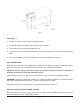
INSTALLATION & OPERATION MANUAL GDC SERIES GAS DUPLEX COOKERS MODELS GDC24 GDC36 GDC48 GDC60 GDC72 ML-52581 ML-52582 ML-52583 ML-52584 ML-52585 MODEL GDC48 VULCAN-HART COMPANY, FORM 30501 (Rev. A, 11-95) P.O. BOX 696, LOUISVILLE, KY 40201-0696, TEL.
IMPORTANT FOR YOUR SAFETY THIS MANUAL HAS BEEN PREPARED FOR PERSONNEL QUALIFIED TO INSTALL GAS EQUIPMENT, WHO SHOULD PERFORM THE INITIAL FIELD START-UP AND ADJUSTMENTS OF THE EQUIPMENT COVERED BY THIS MANUAL. POST IN A PROMINENT LOCATION THE INSTRUCTIONS TO BE FOLLOWED IN THE EVENT THE SMELL OF GAS IS DETECTED. THIS INFORMATION CAN BE OBTAINED FROM THE LOCAL GAS SUPPLIER.
Installation, Operation and Care of GDC SERIES GAS DUPLEX COOKERS KEEP THESE INSTRUCTIONS FOR FUTURE USE GENERAL The GDC Series Gas Duplex Cookers combine a high efficiency gas griddle with adjustable-height, thermostat-controlled electric platens to provide fast production of grilled foods. Vulcan Duplex Cookers are produced with quality workmanship and material. Proper installation, usage and maintenance will result in many years of satisfactory performance.
INSTALLATION CODES AND STANDARDS The GDC Series Gas Duplex Cookers must be installed in accordance with: In the United States: 1. State and local codes. 2. National Fuel Gas Code ANSI Z223.1 (latest edition), available from American Gas Association, 1515 Wilson Blvd., Arlington, VA 22209. 3. National Electrical Code ANSI NFPA No. 70 (latest edition), and with NFPA Standard No.
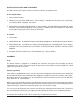
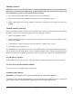
Fig. 1 Stand (Fig. 1) 1. Thread leg extension into fixed nut in griddle frame. 2. Thread adjustable leg through undershelf into leg extension. 3. Tighten both leg extension and adjustable legs. 4. If casters are furnished instead of adjustable legs, the locking swivel casters must be placed in the front. 5. To level the griddle plate, turn the adjustment screw at the bottom of each leg. GAS CONNECTIONS Make the gas connection to the appropriate location on the cooker according to applicable codes.
When test pressures are 1/2 psig (3.45 kPa) or less, the cooker must be isolated from the gas supply piping system by closing its individual shutoff valve. ELECTRICAL CONNECTIONS Make supply connections using insulated copper wire suitable for at least 90°C for the rated load. When initially selecting conduit size, keep in mind the possibility of additional platens being added to the duplex cooker at a later date. The electrical diagram is attached to the hinged control panel cover.
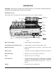
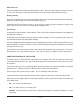
OPERATION WARNING: THE DUPLEX COOKER AND ITS PARTS ARE HOT. BE CAREFUL WHEN OPERATING, CLEANING, AND SERVICING THE DUPLEX COOKER. CONTROLS (Fig. 2) Each griddle zone, one foot wide, and each platen has its own separate controls. TOP - SIDE COOKER HANDLE TWIN - CAM FEET PLATEN GRIDDLE SURFACE GREASE TROUGH MAIN ON / OFF SWITCH AMBER LIGHT GREASE CONTAINER GRIDDLE CONTROLS ON / OFF SWITCH THERMOSTAT TOP- SIDE COOKER CONTROLS PL-40792-1 Fig. 2 Main On-Off Switch — controls power to the pilot igniters.
BEFORE FIRST USE The griddle plate is shipped with a protective coating. Remove this coating before cooking with griddle. Clean the griddle with a damp cloth and mild detergent. Rinse with a clean damp cloth and wipe dry. The griddle must be seasoned prior to first use. See the section titled SEASON GRIDDLE SURFACE for seasoning procedure. LIGHTING PILOTS ON GRIDDLES WITH ELECTRIC IGNITION CAUTION: Do not turn the electric supply on without making sure the gas is flowing to the pilots.
PREHEAT GRIDDLE CAUTION: Care must be exercised not to overheat the griddle plate by setting the thermostats well above recommended temperatures. Overheating the plate may cause plate warpage, and will carbonize any grease on the plate and cause sticking. 1. Set thermostat to desired griddle temperature. Burners should light. 2. Allow 15-20 minutes for the griddle temperature to reach thermostat setting. 3.
After Each Use Clean the griddle with a flexible spatula or griddle scraper. Take care not to contact the platen surfaces as these can be easily scratched, shortening the life of the coating and promoting sticking. During The Day Flush the hot griddle with water and scrape with griddle scraper to reduce carbonized grease build-up. Follow by a light coating of oil to prevent product sticking. Periodically inspect the grease container.
• DO NOT - Use grill cleaners on the platen. Life of the non-stick coating of the platen will vary depending upon the product cooked and the cooking temperature, but its life can be extended by frequent cleaning and by using care not to scratch the surface. When sticking of product eventually occurs and cannot be eliminated by thorough cleaning with a soft cloth and water, it will be necessary to replace the platen surface (see MAINTENANCE).
Tools required: 7 /16 socket (magnetic) 1/4 drive 1 /4 drive universal joint 1 /4 drive 6" extension 1 /4 drive ratchet 1. Remove platen cover (Fig. 3). 2. Remove all bolts from platen. Remove platen surface. (Fig. 4) Fig. 3 Fig. 4 3. Clean surface thoroughly. Make sure all foreign particles are removed from both surfaces (Fig. 5). 4. Attach new surface to platen with new (10) short and (2) long 1/4-20 special bolts and (12) 1/4-20 locknuts. Tighten all bolts and nuts finger tight. (Fig. 6) Fig. 5 Fig.
5. Tighten all bolts and nuts firmly (do not overtighten), with 7/16 wrench, in numerical order as shown in the diagram (Fig. 7). CAUTION: Overtightening can deform the aluminum material of the platen. The holes in the platen surface and the heads on the special bolts are eccentric. Make sure the head of each bolt fits into the hole in the platen surface and stays there until the nut is finger tightened. 6. Reinstall platen cover (Fig. 8) Fig. 7 Fig.
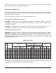
TROUBLESHOOTING PROBLEM POSSIBLE CAUSE Red light won't come on when main switch is on. Not plugged in. Problem with On-Off switch. Building circuit breaker tripped. Problem with lamp in switch. Red light won't go off when Main On-Off or Thermostat switch is on. Problem with On-Off switch. Cooker fails to heat when Thermostat On-Off switch is on. Cooker not plugged in. Problem with Main On-Off switch. Building circuit breaker tripped. Problem with Thermostat On-Off switch. Problem with pilot valve.
PROBLEM POSSIBLE CAUSE Heat doesn't turn off; amber light is off; temperature is above thermostat setting. Problem with thermostat gas valve. Heat doesn't turn off; amber light is on; temperature is above thermostat setting. Problem with temperature controller. Problem with remote set-pot. Fat appears to smoke excessively. Temperature set too high. Moisture in food may be turning into steam. Griddle surface needs cleaning and/or seasoning.
FORM 30501 (Rev.