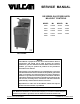
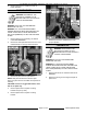
SERVICE MANUAL GR SERIES GAS FRYERS WITH MILLIVOLT CONTROLS MODEL ML MODEL ML GR25 126988 GR35F 126998 GR35 126989 GR45F 126999 GR45 126990 GR65F 135534 GR65 126991 GR85F 135535 GR85 126992 GR35 SHOWN - NOTICE This Manual is prepared for the use of trained Vulcan Service Technicians and should not be used by those not properly qualified. If you have attended a Vulcan Service School for this product, you may be qualified to perform all the procedures described in this manual.
GR SERIES GAS FRYERS TABLE OF CONTENTS GENERAL . . . . . . . . . . . . . . . . . . . . . . . . . . . . . . . . . . . . . . . . . . . . . . . . . . . . . . . . . . . . . . . . . . . . . . . . . . . . . . . . Introduction . . . . . . . . . . . . . . . . . . . . . . . . . . . . . . . . . . . . . . . . . . . . . . . . . . . . . . . . . . . . . . . . . . . . . . . . . . . . Single Floor Model or Battery Fryers . . . . . . . . . . . . . . . . . . . . . . . . . . . . . . . . . . . . . . . . . . . . . . . . . . .
GR SERIES GAS FRYERS - GENERAL GENERAL INTRODUCTION This Service Manual covers specific service information related to the models listed on the front cover. SINGLE FLOOR MODEL OR BATTERY FRYERS Fryers with the Filter-Ready option installed, use the Mobile Filter. For service information related to the Mobile Filter, refer to F24599 MOBILE FILTERS. Filter-Ready fryers are available as single floor models only. The information in the GR Series Service Manual also applies to Non-Filter Ready fryers.
GR SERIES GAS FRYERS - GENERAL KLEENSCREEN FILTERING SYSTEM The Kleenscreen fryer battery still utilizes many of the same components as the single floor model and Non-Filter ready battery fryers. The new Kleenscreen filtering system has been integrated into the GR Series fryer battery. The filter is housed in a pull-out drawer assembly at the base of the fryer. The filtering components in the drawer include a stainless steel filter tank, crumb-catch basket and a dual element mesh filter screen.
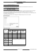
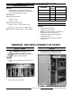
GR SERIES GAS FRYERS - REMOVAL AND REPLACEMENT OF PARTS Input BTU Rating SPECIFICATIONS GR SERIES Electrical • 120VAC supply for Filter-Ready fryers and Kleenscreen filter models only. The filter pump motor draws approximately 5 amps. NO. OF BTU/HR/SECTION TUBES GR25, GR25F 2 60,000 GR35, GR35F 3 90,000 Gas Pressures GR45, GR45F 4 120,000 Manifold (per fryer section): GR65, GR65F 5 150,000 • Natural - 4" W.C. GR85, GR85F 5 150,000 • Propane - 10" W.C.
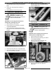
GR SERIES GAS FRYERS - REMOVAL AND REPLACEMENT OF PARTS 2. When replacing door, install screws and tighten top and bottom screws enough to hold door in place. 3. Close door, check alignment and adjust if necessary. 4. Finish tightening screws to fully secure. 6. Remove screws securing capillary tube mounting clips to the fry tank heat tube then remove capillary tube. 7. Reverse procedure to install and check for proper operation.
GR SERIES GAS FRYERS - REMOVAL AND REPLACEMENT OF PARTS 5. Remove the capillary tube retaining and packing nuts, from the bottom of fry tank. 6. Remove screws securing capillary tube mounting clips to the fry tank heat tube then remove capillary tube. 3. Lift main burner up and tilt the top of burner toward fry tank until it clears the gas orifice at the bottom. A. 7. Lift main burner from fryer. Reverse procedure to install.
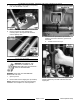
GR SERIES GAS FRYERS - REMOVAL AND REPLACEMENT OF PARTS GAS COMBINATION VALVE WARNING: DISCONNECT THE ELECTRICAL POWER TO THE MACHINE AND FOLLOW LOCKOUT / TAGOUT PROCEDURES. WARNING: SHUT OFF THE GAS BEFORE SERVICING THE UNIT. WARNING: ALL GAS JOINTS DISTURBED DURING SERVICING MUST BE CHECKED FOR LEAKS. CHECK WITH A SOAP AND WATER SOLUTION (BUBBLES). DO NOT USE AN OPEN FLAME. NOTE: Gas combination valves are not serviceable and should not be disassembled.
GR SERIES GAS FRYERS - REMOVAL AND REPLACEMENT OF PARTS 6. Reverse procedure to install and check for proper operation. PILOT BURNER WARNING: DISCONNECT THE ELECTRICAL POWER TO THE MACHINE AND FOLLOW LOCKOUT / TAGOUT PROCEDURES. WARNING: SHUT OFF THE GAS BEFORE SERVICING THE UNIT. WARNING: ALL GAS JOINTS DISTURBED DURING SERVICING MUST BE CHECKED FOR LEAKS. CHECK WITH A SOAP AND WATER SOLUTION (BUBBLES). DO NOT USE AN OPEN FLAME. 1. 2. Remove burners (as necessary) as outlined under MAIN BURNERS. 6.
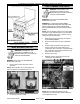
GR SERIES GAS FRYERS - REMOVAL AND REPLACEMENT OF PARTS 8. Remove pilot burner as outlined under PILOT BURNER. 9. Remove control thermostat as outlined under CONTROL THERMOSTAT. 10. Remove high limit thermostat as outlined under HIGH LIMIT THERMOSTAT. 11. Remove gas manifold and hanger assembly from the fryer. 3. Reverse procedure to install and check for proper operation. WARNING: DISCONNECT THE ELECTRICAL POWER TO THE MACHINE AND FOLLOW LOCKOUT / TAGOUT PROCEDURES.
GR SERIES GAS FRYERS - REMOVAL AND REPLACEMENT OF PARTS 21. Reverse procedure to install all the parts removed from original fry tank onto replacement fry tank, then install the assembly. FILTER VALVE AND DISCARD VALVE SWITCHES WARNING: DISCONNECT THE ELECTRICAL POWER TO THE MACHINE AND FOLLOW LOCKOUT / TAGOUT PROCEDURES. 1. Open the door to the fryer section being serviced. 2. Remove burners (as necessary) as outlined under MAIN BURNERS. 3. 4.
GR SERIES GAS FRYERS - SERVICE PROCEDURES AND ADJUSTMENTS SERVICE PROCEDURES AND ADJUSTMENTS WARNING: CERTAIN PROCEDURES IN THIS SECTION REQUIRE ELECTRICAL TEST OR MEASUREMENTS WHILE POWER IS APPLIED TO THE MACHINE. EXERCISE EXTREME CAUTION AT ALL TIMES. IF TEST POINTS ARE NOT EASILY ACCESSIBLE, DISCONNECT POWER AND FOLLOW LOCKOUT / TAGOUT PROCEDURES, ATTACH TEST EQUIPMENT AND REAPPLY POWER TO TEST. CONTROL THERMOSTAT CALIBRATION NOTE: Check the level of shortening in fry tank before proceeding.
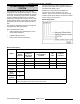
GR SERIES GAS FRYERS - SERVICE PROCEDURES AND ADJUSTMENTS GAS MANIFOLD PRESSURE ADJUSTMENT WARNING: SHUT OFF THE GAS SUPPLY BEFORE SERVICING THE UNIT. GAS PRESSURE (INCHES W.C.) GAS TYPE MANIFOLD LINE RECOMMENDED MIN MAX Natural 4 7 5 Propane 10 11 11 14 NOTE: If the incoming line pressure is less than the minimum stated, then the manifold pressure cannot be set correctly. 1. Open the door and turn gas combination valve knob/extension arm to off. 2.
GR SERIES GAS FRYERS - SERVICE PROCEDURES AND ADJUSTMENTS A. If adjustment is necessary, continue with procedure. MILLIVOLT CONTROLS TEST 1. Verify millivolt control circuit wiring is correct and connections are clean and secure. 2. Verify pilot burner flame is adjusted properly as outlined under PILOT BURNER FLAME ADJUSTMENT. 3.
GR SERIES GAS FRYERS - ELECTRICAL OPERATION ELECTRICAL OPERATION COMPONENT FUNCTION FRYER CONTROLS Control Thermostat . . . . . . . . . . . Regulates shortening temperature at the selected set point. Temperature range from off to 200/F thru 400/F. Thermopile . . . . . . . . . . . . . . . . . . When heated by the pilot burner flame, generates DC millivolts to energize pilot valve coil and main valve coil on the gas combination valve. Gas Combination Valve . . . . . . . . . . . . . . . . . . . . . . .
GR SERIES GAS FRYERS - ELECTRICAL OPERATION COMPONENT LOCATION GR35 NON FILTER READY SHOWN GR45 FILTER READY SHOWN 2GR45F KLEENSCREEN FRYER BATTERY SHOWN F25125 (March 2003) Page 16 of 24
GR SERIES GAS FRYERS - ELECTRICAL OPERATION 1. SEQUENCE OF OPERATION Conditions A. Fryer connected to correct supply voltage and is properly grounded. Refer to schematic diagram 7825. B. Shortening between 300/F and 350/F. 1. NOTE: Oil should not be filtered outside of this temperature range. At lower temperatures the oil is thicker which may increase filtering time and place a greater load on the pump. At higher oil temperatures, oil seal life is decreased. Millivolt Controls Conditions. A.
GR SERIES GAS FRYERS - ELECTRICAL OPERATION SCHEMATIC DIAGRAM Millivolt Controls F25125 (March 2003) Page 18 of 24
GR SERIES GAS FRYERS - ELECTRICAL OPERATION WIRING DIAGRAMS Millivolt Controls Page 19 of 24 F25125 (March 2003)
GR SERIES GAS FRYERS - ELECTRICAL OPERATION Junction Box, Kleenscreen Filtering System F25125 (March 2003) Page 20 of 24
GR SERIES GAS FRYERS - ELECTRICAL OPERATION Frymate (Dump Station) Page 21 of 24 F25125 (March 2003)
GR SERIES GAS FRYERS - TROUBLESHOOTING TROUBLESHOOTING ALL MODELS SYMPTOMS POSSIBLE CAUSES Pilot burner will not light. 1. 2. 3. 4. 5. 6. Gas supply off. High limit thermostat open or malfunction. Incorrect gas type. Pilot burner flame adjustment too low. Pilot burner orifice obstructed or incorrect. Gas combination valve malfunction. Pilot burner lights but will not maintain flame. 1. 2. 3. 4. 5. 6. Pilot burner flame adjustment too low. Pilot burner orifice obstructed or incorrect.
GR SERIES GAS FRYERS - TROUBLESHOOTING FRYMATE (DUMP STATION) WITH OPTIONAL HEATER SYMPTOM POSSIBLE CAUSES No heat. 1. 2. 3. 4. Unplugged. Power switch off or inoperative. Main circuit breaker off or open. Malfunctioning heat assembly. KLEENSCREEN FILTERING SYSTEM SYMPTOM POSSIBLE CAUSES Oil not filtering, pump motor is on. 1. Filter screen plugged. 2. Clog in filter system lines.
GR SERIES GAS FRYERS - CONDENSED SPARE PARTS LIST CONDENSED SPARE PARTS LIST KLEENSCREEN FILTER PART NUMBER DESCRIPTION 411496-B4 Lighted Rocker Switch, Filter 417792-1 Pump and Motor Assy, Filter (120VAC) NOTES GR SERIES GAS FRYERS WITH MILLIVOLT CONTROL PART NUMBER DESCRIPTION 419999-2 Thermostat, Reed Switch 419670-2 High Limit Thermostat (w/stuffing box) 410839-4 Thermopile, Millivolt (manual ign.