INSTALLATION & OPERATION MANUAL GAS 2/3 JACKETED STATIONARY AND TILTING KETTLES MODELS K20GL K40GL K60GL K20GLT K40GLT K60GLT ML-136090 ML-136091 ML-136092 ML-136094 ML-136095 ML-136096 K40GL For additional information on Vulcan-Hart or to locate an authorized parts and service provider in your area, visit our website at www.vulcanequipment.com VULCAN-HART DIVISION OF ITW FOOD EQUIPMENT GROUP, LLC WWW.VULCANEQUIPMENT.COM 3600 NORTH POINT BLVD.
GAS KETTLES IMPORTANT FOR YOUR SAFETY THIS MANUAL HAS BEEN PREPARED FOR PERSONNEL QUALIFIED TO INSTALL GAS EQUIPMENT, WHO SHOULD PERFORM THE INITIAL FIELD START-UP AND ADJUSTMENTS OF THE EQUIPMENT COVERED BY THIS MANUAL. POST IN A PROMINENT LOCATION THE INSTRUCTIONS TO BE FOLLOWED IN THE EVENT THE SMELL OF GAS IS DETECTED. THIS INFORMATION CAN BE OBTAINED FROM THE LOCAL GAS SUPPLIER.
GAS KETTLES CONTENTS GENERAL ...........................................................................................................................................4 INSTALLATION ...................................................................................................................................5 Unpacking......................................................................................................................................5 Installation Codes and Standards..................
GAS KETTLES INSTALLATION, OPERATION AND MAINTENANCE OF KGL AND KGLT SERIES GAS KETTLES SAVE THESE INSTRUCTIONS FOR FUTURE USE GENERAL Vulcan gas 2/3 jacketed kettles are produced with quality workmanship and material. Proper installation, usage and maintenance will result in many years of satisfactory performance. It is suggested that you thoroughly read this entire manual and carefully follow all of the instructions provided.
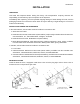
GAS KETTLES INSTALLATION UNPACKING This kettle was inspected before leaving the factory. The transportation company assumes full responsibility for safe delivery upon acceptance of the shipment. Immediately after unpacking, check for possible shipping damage. If kettle damage is found, save the packaging material and contact the carrier within 15 days of delivery. Freight damage is not covered under Vulcan Warranty.
GAS KETTLES GAS CONNECTIONS Gas supply connections and any pipe joint compound must be resistant to the action of propane gases. Codes require that a gas shutoff valve be installed in the gas line ahead of the kettle. Connect the gas supply line to the gas valve on the kettle. Make sure the pipes are clean and free of obstructions, dirt and piping compound. The gas line must be capable of delivering gas to the kettle without excessive pressure drop at the rate specified on the nameplate.
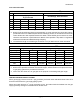
GAS KETTLES Gas Connection Data ID / 2" 3 / 4" 1" 11/4" 1. 1 FLEXIBLE GAS CONNECTORS BTU/hr.
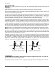
GAS KETTLES GAS AND ALTITUDE CONVERSION The kettle can be field converted to propane gas or for operation at altitudes above 2000ft elevation.A manometer that reads in 1/100" WC and portable combustion analyzer are required. Natural gas to Propane gas conversion: 1. Remove the r ight side controls compartment side panel. 2. Locate the gas combination valve located in the bottom of the controls compartment. 3. Turn S1 screw located right of manifold pressure port (Fig.
GAS KETTLES Altitude: 1. Remove the right side controls compartment side panel. 2. Locate the gas combination valve located in the bottom of the controls compartment. 3. Turn S2 screw (Fig. 1) (using 5/64” Allen wrench), ½ turn clock wise 4. Turn the unit on. 5. Try five (5) times igniting the burner, if burner fails to ignite repeat step 3. 6. Inlet pressure setting: a. Natural Gas: 5-7” WC b. Propane: 11-13” WC 7. Fill the unit half way with cold water. 8.
GAS KETTLES LOCATION Position the kettle in its final location. Check that there are sufficient clearances for operating and servicing the kettle, and for proper clearance of the cover when raised. Keep the kettle free and clear from all combustible substances. Minimum clearance from combustible and non-combustible construction is 2" (5.0 cm) at the rear and 6" (15.2 cm) at each side. The kettle draw off valve should be located near a floor drain. Do not obstruct the flow of air into and around the kettle.
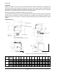
GAS KETTLES Tilting Kettle "P" "Q" "E" "M" "F" ADD 2" FOR PLUG VALVE "L" SHOWN WITH OPTIONAL DRAW-OFF VALVE ( 2" PLUG VALVE) 12.0 [305] "N" "K" "A" 9.3 [235] "R" 17.6 [446] 4.1 [104] ELEC CONNECTION "B" SHOWN WITH OPTIONAL DRAW-OFF VALVE AND LID (3" COMPRESSION VALVE) "C" "J" GAS CONNECTION SHOWN WITH OPTIONAL DRAW-OFF VALVE ( 2" COMPRESSION VALVE) TRUE WORKING CAPACITY A B C 20 gallons 21.6 15.2 76 liters 549 386 K40GLT 40 gallons 25.
GAS KETTLES OPERATION The kettle and its parts are hot. Use care when operating, cleaning or servicing the kettle. CONTROLS AND INDICATORS Control Function Vacuum/Pressure Gauge Thermostat Low Water Indicator (Red) Power ON/OFF Switch Power ON indicator (Amber) Heater Light (Amber) Ignition Failure Indicator (Red) Water Level Sight Glass Crank Handle Indicates the vacuum (in inches) and pressure (in PSI) inside the kettle jacket. Regulates kettle temperature from warm to rolling boil.
GAS KETTLES BEFORE OPERATION 1. Check Gauge Pressure – should read 20-30 In. Hg. below zero when cold. (Higher reading indicates air in jacket. See Venting instructions.) 2. Check to make sure gas supply valve is turned on. 3. Check water level in sight glass. Water level should be in the middle of the sight glass. If level is less than ¼ of the sight glass or the low water light is illuminated, water must be added to the jacket (See Jacket Water Level.) Do not over fill. 4.
GAS KETTLES VENTING While the kettle is cold, check the vacuum/pressure gauge. The gauge should be in the vacuum zone measuring between 20 to 30 in. Hg (84 to 100kPa). If not, there is air in the jacket and it must be removed by venting for proper heating. Perform the venting procedure located in the Maintenance section of this manual. RESERVOIR JACKET WATER LEVEL CHECK During use, the reservoir water level must be maintained high to cover the entire heating zone.
GAS KETTLES STAINLESS STEEL EQUIPMENT CARE AND CLEANING (Supplied courtesy of NAFEM. For more information, visit their web site at www.nafem.org) Contrary to popular belief, stainless steels ARE susceptible to rusting. Corrosion on metals is everywhere. It is recognized quickly on iron and steel as unsightly yellow/ orange rust. Such metals are called “active” because they actively corrode in a natural environment when their atoms combine with oxygen to form rust.
GAS KETTLES 4. Treat your water. Though this is not always practical, softening hard water can do much to reduce deposits. There are certain filters that can be installed to remove distasteful and corrosive elements. To insure proper water treatment, call a treatment specialist. 5. Keep your food equipment clean. Use alkaline, alkaline chlorinated or non-chloride cleaners at recommended strength. Clean frequently to avoid build-up of hard, stubborn stains.
GAS KETTLES CLEANING The kettle and its parts are hot. Use care when operating, cleaning or servicing the kettle. Disconnect the electrical power to the machine and follow lockout / tagout procedure, before cleaning or servicing.. Never spray the exterior of the kettle or control box with water under any condition. Failure to comply will void the warranty.
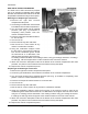
GAS KETTLES PLUG VALVE CLEANING INSTRUCTIONS Daily After Use Remove draw-off valve plug for cleaning (Fig. 3). 1. Unscrew the retaining ring and remove it and the bottom washer. 2. Pull the valve plug straight up to remove from valve body. 3. Wash valve body, plug, washer and retaining ring with mild soap and water, and then rinse. 4. Leave assembly apart to air dry. Valve Plug Care should be taken not to scratch, ding or dent the valve plug to prevent valve leakage.
GAS KETTLES MAINTENANCE The kettle and its parts are hot. Use care when operating, cleaning or servicing the kettle. VENTING When cold, the pressure gauge vacuum measuring zone should be between 20 to 30 In. Hg (84 to 100kPa). If the vacuum indicator is not within this range, perform the following: 1. Ensure that the water level in the jacket is approx. 1/2 in the sight glass. 2. With the kettle empty, place the power switch to the ON position. 3. Set the temperature control to the max heat setting.
GAS KETTLES TROUBLESHOOTING Problem Will Not Turn On, no power light Low Water Light On or Low water in Sight Glass Not Heating, Ignition Fail Light Is On Kettle not in vacuum when cold or will not boil when up to pressure F-35461 (June 2012) Possible Causes / Suggested Corrective Action Kettle is not plugged in / Plug in power cord. Power switch is off / Turn on power switch.