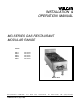
INSTALLATION & OPERATION MANUAL MG SERIES GAS RESTAURANT MODULAR RANGE MODEL MG12 MG24 MG36 MG48 MG60 ML-52549 ML-52514 ML-52522 ML-52523 ML-52524 MODEL MG12 VULCAN-HART COMPANY, FORM 30832 Rev. E (Sept. 2000) P.O. BOX 696, LOUISVILLE, KY 40201-0696, TEL.
IMPORTANT FOR YOUR SAFETY THIS MANUAL HAS BEEN PREPARED FOR PERSONNEL QUALIFIED TO INSTALL GAS EQUIPMENT, WHO SHOULD PERFORM THE INITIAL FIELD START-UP AND ADJUSTMENTS OF THE EQUIPMENT COVERED BY THIS MANUAL. POST IN A PROMINENT LOCATION THE INSTRUCTIONS TO BE FOLLOWED IN THE EVENT THE SMELL OF GAS IS DETECTED. THIS INFORMATION CAN BE OBTAINED FROM THE LOCAL GAS SUPPLIER.
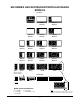
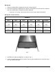
MG SERIES GAS RESTAURANT MODULAR RANGE MODELS TOP VIEWS MG12 MG36ER MG48Z MG48ZT MG60Z MG60ZT MG36X MG36XT MG48X MG48XT MG60X MG60XT MG24F MG24FT MG36F MG36FT MG48F MG48FT MG60F MG60FT MG24S MG24ST MG36S MG36ST MG48S MG48ST MG60S MG60ST MG36 MG48 MG60 MG24 Indicates step up burner construction FRONT VIEWS MG12 MG24 MG36 MG48 MG60 PL-53565 MODEL SUFFIX DESIGNATIONS S = 12" Griddle F = 24" Griddle X = 36" Griddle NOTE: RANGE MAY BE ORDERED WITH ONE 12" HOT TOP SECTION IN PLACE OF T
TABLE OF CONTENTS MG SERIES GAS RESTAURANT MODULAR RANGE MODELS ................................................... 3 INSTALLATION ................................................................................................................................... 5 Uncrating ................................................................................................................................. 5 Location ................................................................................................
Installation, Operation and Care of MG SERIES GAS RESTAURANT MODULAR RANGE KEEP THIS MANUAL FOR FUTURE REFERENCE Vulcan ranges are produced with quality workmanship and material. Proper installation, usage and maintenance of your range will result in many years of satisfactory performance. The manufacturer suggests that you thoroughly read this entire manual and carefully follow all of the instructions provided. INSTALLATION UNCRATING This range was inspected before leaving the factory.
INSTALLATION CODES AND STANDARDS For proper installation procedures in the United States of America, refer to: 1. State and local codes. 2. National Fuel Gas Code, ANSI-Z223.1 (latest edition). Copies may be obtained from The American Gas Assn., Inc., 1515 Wilson Blvd., Arlington, VA 22209. 3. National Electrical Code ANSI/NFPA-70 (latest edition). Copies may be obtained from The National Fire Protection Assn., Batterymarch Park, Quincy, MA 02269. In Canada, refer to: 1. Local codes. 2.
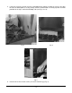
4. Rest the griddle plate in a secure place. 5. Thermostatically controlled griddles are shipped without the thermostat bulb in the “V” shield. The bulb must be installed by the installer to prevent damage to the griddle and the thermostat (not covered by the warranty). Exercise caution when placing brick in a thermostatically controlled griddle section. DO NOT hit thermostat bulb while installing bricks. The thermostat bulb is a sensitive device and may be easily knocked out of adjustment.
. Check to ensure that all bricks and burners are secure. 9. Carefully replace the griddle top section. Be sure that the griddle capillary and bulb(s) are not in a position to be damaged. a. Gently pull the griddle capillary toward the front of the range and out from under the griddle area. b. While two people (one to each side of the griddle) are lowering the griddle into place, the third person must gently feed the griddle thermostat bulb(s) through the “V” shield(s) until completely covered.
Backsplash 1. Remove the backsplash components from the crating materials. 2. Check the backsplash component parts against the list below to ensure that all the required parts for the backsplash installation have been obtained. • If any parts are missing, contact your dealer or closest parts depot immediately. Backsplash Component Parts MODELS MG12 MG24 MG36 MG48 MG60 Std. 4" (10 cm) Std.
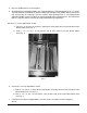
5. It may be necessary to pull the heat shield bottom out slightly in order to clear the flue box. Be sure the backsplash is resting evenly and the channel holes are lining up with the holes provided in the right- and left-hand body side (see Fig’s. 3 & 4). PL-21424 Fig. 3 Fig. 4 PL-40045 PL-40045 Fig. 5 6. Install six #10 sheet metal screws (3 to each channel leg) (Fig. 5).
LEVELING Check the leveling of the range. Place a carpenter’s level across the range top plates. Level front to back and side to side. To adjust the leveling, tilt the range to one side and, using channel locks, unscrew the adjustable leg insert as required. Repeat this procedure as necessary for each leg. GAS CONNECTIONS CAUTION: All gas supply connections and any pipe joint compound used must be resistant to the action of propane gases. Connect gas supply.
WARNING: PRIOR TO LIGHTING, CHECK ALL JOINTS IN THE GAS SUPPLY LINE FOR LEAKS. USE SOAP AND WATER SOLUTION. DO NOT USE AN OPEN FLAME. After piping has been checked for leaks, all piping receiving gas should be fully purged to remove air. TESTING THE GAS SUPPLY SYSTEM When gas supply pressure exceeds 1⁄2 psig (3.45 kPa), the range and its individual shutoff valve must be disconnected from the gas supply piping system. When gas supply pressure exceeds 1⁄2 psig (3.
Nightly Shutdown: Turn burner valve OFF; pilot will remain lit. Complete Shutdown 1. Turn burner valve OFF; pilot will remain lit. 2. Turn main gas supply OFF. Open Top Burners 1. Turn main gas supply ON. 2. Turn all top burner valve knobs ON to purge gas line of air. 3. Turn top burner valve knobs OFF. 4. Wait 30 seconds. 5. Using a taper, light the open top pilot (Fig. 7). Fig. 7 6. If pilot fails to light, wait 5 minutes and repeat Steps 1 thru 5. 7.
OPERATION WARNING: THE RANGE AND ITS PARTS ARE HOT. BE VERY CAREFUL WHEN OPERATING, CLEANING OR SERVICING THE RANGE. CONTROLS OPEN TOP BURNER KNOB — Regulates gas flow to top burners. To increase heat, turn knob counterclockwise; to decrease, turn knob clockwise. HOT TOP OR GRIDDLE TOP BURNER KNOB — Regulates gas flow to the hot top or griddle top burner. To increase heat, turn knob counterclockwise; to decrease, turn knob clockwise.
Vulcan painted surfaces may be cleaned using a soft cloth and mild detergent solution. Ranges Daily: While still warm, wipe top with a soft cloth or other grease absorbing material to remove spillovers, grease, etc., before they burn in. A crust on top of the hot top range looks unsightly and slows down cooking speed because it reduces the flow of heat to the utensil. Empty the grease pan daily or as often as necessary. CAUTION: Remove the grease pan slowly and be careful of liquid wave action.
MAINTENANCE WARNING: THE RANGE AND ITS PARTS ARE HOT. BE VERY CAREFUL WHEN OPERATING, CLEANING OR SERVICING THE RANGE. VENT When cool, check the flue vent every six months for obstructions. SERVICE AND PARTS INFORMATION To obtain service and parts information concerning this modular range, contact the Vulcan-Hart Service Agency in your area (refer to listing supplied with the modular range), or Vulcan-Hart Service Department at the address or phone number shown on the front cover of this manual.