SERVICE MANUAL VHX BOILER BASE SERIES HIGH EFFICIENCY ELECTRIC STEAMER VHX24E ML-126852 VHX24E5 ML-126853 MHB24E ML-126857 (BASE ONLY) VHX24E SHOWN - NOTICE This Manual is prepared for the use of trained Vulcan Service Technicians and should not be used by those not properly qualified. If you have attended a Vulcan Service School for this product, you may be qualified to perform all the procedures described in this manual. This manual is not intended to be all encompassing.
VHX SERIES STEAMERS TABLE OF CONTENTS GENERAL . . . . . . . . . . . . . . . . . . . . . . . . . . . . . . . . . . . . . . . . . . . . . . . . . . . . . . . . . . . . . . . . . . . . . . . . . . . . . . . . Installation, Operation and Cleaning . . . . . . . . . . . . . . . . . . . . . . . . . . . . . . . . . . . . . . . . . . . . . . . . . . . . . . . . Introduction . . . . . . . . . . . . . . . . . . . . . . . . . . . . . . . . . . . . . . . . . . . . . . . . . . . . . . . . . . . . . . . . . . . . . . . .
VHX SERIES STEAMERS ELECTRICAL OPERATION . . . . . . . . . . . . . . . . . . . . . . . . . . . . . . . . . . . . . . . . . . . . . . . . . . . . . . . . . . . . . . . . . . Component Function . . . . . . . . . . . . . . . . . . . . . . . . . . . . . . . . . . . . . . . . . . . . . . . . . . . . . . . . . . . . . . . . . . . Cabinet Base Boiler Controls . . . . . . . . . . . . . . . . . . . . . . . . . . . . . . . . . . . . . . . . . . . . . . . . . . . . . . . . . Cooking Compartment Controls . . . . . . .
VHX SERIES STEAMERS - GENERAL GENERAL Cooking Compartments Control Panel INSTALLATION, OPERATION AND CLEANING Refer to the Installation and Operation Manual for specific instructions. INTRODUCTION Steam Cooking Convection cooking in pressure-less steaming compartments will steam cook fresh foods or will steam defrost and cook frozen foods providing the maximum color, flavor and nutritional value with the least expenditure of energy and labor.
VHX SERIES STEAMERS - GENERAL Boiler Code Descriptions Vulcan-Hart incorporates redundant controls in compliance with the CSD-1 controls and safety devices for boiler construction on the high efficiency steamer models. A description of the code is listed below. CSD-1 Construction - Redundant controls in the electrical safety circuits that, if tripped, must manually be reset after the condition causing the trip subsides.
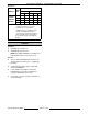
VHX SERIES STEAMERS - COMPONENT FUNCTION Electrical AMPERAGE MODELS TOTAL KW 1 PHASE 3 PHASE 208V 240V 208V 240V 480V VHX24E, VHX24E5, MHB24E NOTES: 24 116 100 67 58 29 36 --- --- 100 87 44 42 --- --- 117 --- --- 48 --- --- --- 116 58 1. Amperage values in the table are nominal. Tolerance is +5/-10%. 2. Voltage values are @ 60HZ. 3. 24KW 3 phase is standard for both models. If a 24KW single phase connection is needed, the machine is field convertible at the terminal block.
VHX SERIES STEAMERS - REMOVAL AND REPLACEMENT OF PARTS REMOVAL AND REPLACEMENT OF PARTS PRESSURE SWITCH CONTROL BOX COMPONENTS WARNING: DISCONNECT THE ELECTRICAL POWER TO THE MACHINE AND FOLLOW LOCKOUT / TAGOUT PROCEDURES. CAUTION: Certain components in this system are subject to damage by electrostatic discharge during field repairs. A field service grounding kit is available to prevent damage. The field service grounding kit must be used anytime a control board is handled. 1.
VHX SERIES STEAMERS - REMOVAL AND REPLACEMENT OF PARTS MAIN CONTROL BOX COMPONENTS WARNING: DISCONNECT THE ELECTRICAL POWER TO THE MACHINE AND FOLLOW LOCKOUT / TAGOUT PROCEDURES. CAUTION: Certain components in this system are subject to damage by electrostatic discharge during field repairs. A field service grounding kit is available to prevent damage. The field service grounding kit must be used anytime a control board is handled. B.
VHX SERIES STEAMERS - REMOVAL AND REPLACEMENT OF PARTS WATER LEVEL GAUGE ASSEMBLY WARNING: DISCONNECT THE ELECTRICAL POWER TO THE MACHINE AND FOLLOW LOCKOUT / TAGOUT PROCEDURES. 1. Remove right side panel. NOTE: If right side panel is not accessible, open the cabinet door and remove control panel to access from front. 2. 4. To remove: A. Contactors. 1) B. Remove from socket. Relay Board. 1) 5. Release catch at the base of contactor and remove from DIN rail. Relays. 1) C.
VHX SERIES STEAMERS - REMOVAL AND REPLACEMENT OF PARTS B. Insert one end of glass tube into top gauge fitting then align opposite end of tube with bottom gauge fitting. C. Lower the glass tube into bottom gauge fitting then center the tube between top & bottom gauge fittings. D. Hold glass tube in place and hand tighten the bottom packing nut then top. E. Tighten each packing nut and additional 1/2 turn. CAUTION: Do not over tighten packing nuts or damage to glass tube may occur. 6.
VHX SERIES STEAMERS - REMOVAL AND REPLACEMENT OF PARTS HEATING ELEMENT MOUNTING PLATE WARNING: DISCONNECT THE ELECTRICAL POWER TO THE MACHINE AND FOLLOW LOCKOUT / TAGOUT PROCEDURES. 6. Loosen both conduit locking nuts (1 1/2" & 3/8") in main control box. 7. Loosen conduit nut (1 1/2") on elbow connected to main control box. 8. Remove mounting bolts for main control box. A. 9. 1. Remove heating elements as outlined under HEATING ELEMENTS. 2.
VHX SERIES STEAMERS - REMOVAL AND REPLACEMENT OF PARTS C. Position heating element mounting plate with mounting studs for the element cover at the top. NOTE: When installing heating element mounting plate, install and tighten the mounting bolts as indicated to ensure the mounting plate is flush with boiler flange and gasket is evenly compressed. If bolt is not threading properly by hand, clean out the threads with a 3/8 x 16 tap. D.
VHX SERIES STEAMERS - REMOVAL AND REPLACEMENT OF PARTS LEFT SIDE VIEW SHOWN 18. Separate union at boiler drain. LEFT SIDE VIEW SHOWN 19. On models with cooking compartments: A. Remove the left and right access panels between the cooking compartments and boiler base. B. Disconnect flexible steam supply line from boiler tee to cooking compartments and remove the line. C. Disconnect both drain lines from cooking compartments to condenser drain box and remove the lines. 20.
VHX SERIES STEAMERS - REMOVAL AND REPLACEMENT OF PARTS 5. Adjust the door as outlined in DOOR SEALING ADJUSTMENT under COOKING COMPARTMENT. NOTE: Do not over tighten gasket plate screws as this will compress the gasket excessively and interfere with proper door sealing. NOTE: Damage to the gasket sealing surface, such as nicks or cuts, will cause steam leakage. 3. To install: A. On the two replacement descalers, stretch the coiled wire (cathode) at the top to elongate the wire then form an open loop.
VHX SERIES STEAMERS - REMOVAL AND REPLACEMENT OF PARTS 4. Remove the nuts and spacers from the handle screws and remove the handle from the door. Pull the inner door panel out from the door housing with the gasket plate and gasket still attached. 4. Remove the screws from the side edge of the door that secure the latch mechanism and remove the latch from the door. NOTE: When installing, the latch lever must rest on top of the handle latch screw. 5.
VHX SERIES STEAMER - SERVICE PROCEDURES AND ADJUSTMENTS SERVICE PROCEDURES AND ADJUSTMENTS WARNING: CERTAIN PROCEDURES IN THIS SECTION REQUIRES ELECTRICAL TEST OR MEASUREMENTS WHILE POWER IS APPLIED TO THE MACHINE. EXERCISE EXTREME CAUTION AT ALL TIMES. IF TEST POINTS ARE NOT EASILY ACCESSIBLE, DISCONNECT POWER AND FOLLOW LOCKOUT / TAGOUT PROCEDURES, ATTACH TEST EQUIPMENT AND REAPPLY POWER TO TEST. BOILER Inspection Periodic service must be performed as outlined in the BOILER procedures.
VHX SERIES STEAMER - SERVICE PROCEDURES AND ADJUSTMENTS 1. Access the descalers (cathodic protectors) as outlined in REMOVAL AND REPLACEMENT OF PARTS. 2. Inspect the two descalers hanging in boiler. NOTE: As descalers erode over time, the diameter decreases while the length increases. NOTE: A new descaler is approximately 1 3/8" diameter and 3 3/4" long at the core. A.
VHX SERIES STEAMER - SERVICE PROCEDURES AND ADJUSTMENTS 1) Verify wire color connections are correct at probe numbers 50, 51 & 52, and at the water level control board. A. Turn power switch on and allow boiler to fill. Do not press the reset switch to start heating. 2) Turn power switch off. B. 3) Remove probe assembly, clean lime scale build-up from the probes and compare probe lengths to drawing. Turn water supply off and open the ball valve on probe housing assembly.
VHX SERIES STEAMER - SERVICE PROCEDURES AND ADJUSTMENTS 9. B. Verify Low Water light is lit (front control panel). 3. Press reset switch and verify high pressure light turns off. C. Verify 120VAC is on Aux LLCO COM, and 0 volt is on Aux LLCO N.O. contacts. 4. When green ready light comes on, press reset switch to begin heating (low water light turns off). When water level reaches Aux LLCO probe as boiler continues to fill: A. B. C. A. Allow boiler to fully pressurize.
VHX SERIES STEAMER - SERVICE PROCEDURES AND ADJUSTMENTS NOTE: For every click of the adjustment wheel, the pressure setting is changed approximately 1/8 PSI. HIGH LIMIT PRESSURE SWITCH ADJUSTMENT NOTE: Before the high limit pressure switch can be adjusted, the cycling pressure switch must be temporarily removed from the boiler control circuit. This allows the boiler to pressurize above the normal operating range.
VHX SERIES STEAMER - SERVICE PROCEDURES AND ADJUSTMENTS 3. To check boiler fill valve: A. Verify 120VAC to solenoid valve coil. B. If voltage is correct but valve is not opening (little or no water flow), turn power switch off and disconnect power to machine. 1) Remove lead wires from coil and check for continuity. 2) If no continuity is measured, install a replacement solenoid valve and check for proper operation. 3) C. 4.
VHX SERIES STEAMER - SERVICE PROCEDURES AND ADJUSTMENTS HEATING ELEMENT TEST COOKING COMPARTMENT VOLTAGE KW PER ELEMENT AMPS PER ELEMENT OHMS PER ELEMENT 208 9.0 14.4 14.4 240 9.0 12.5 19.2 NOTE: Before proceeding with intake shut-off valve adjustment, monitor boiler pressure gauge and verify boiler is operating between 10-12 PSI. If boiler pressure adjustment is necessary, refer to CYCLING PRESSURE SWITCH ADJUSTMENT. 480 9.0 6.3 76.
VHX SERIES STEAMER - SERVICE PROCEDURES AND ADJUSTMENTS Door Sealing Adjustment 1. Check door gasket condition. If damaged or worn, replace as outlined under COOKING COMPARTMENT DOOR(S) in REMOVAL AND REPLACEMENT OF PARTS. 2. Loosen screws until the screw heads no longer touch gasket plate. 3. Tighten screws until the screw heads touch gasket plate and begin counting turns. Tighten all screws approximately two turns. 4. Close the door and check for proper operation. A.
VHX SERIES STEAMER - ELECTRICAL OPERATION ELECTRICAL OPERATION COMPONENT FUNCTION CABINET BASE BOILER CONTROLS Power Switch . . . . . . . . . . . . . . . . Controls 120VAC to the boiler control circuit. Reset Switch (Manual) . . . . . . . . . Resets the low water level safety circuit on initial startup or the occurrence of a low water condition. Also, resets the high pressure level safety circuit on initial startup or the occurrence of a high pressure condition which allows heating to start.
VHX SERIES STEAMER - ELECTRICAL OPERATION Supply Voltage Transformer . . . . Provides 120VAC to the boiler control and cooking compartment control circuits. Cycling Contactors B & D . . . . . . Supplies line voltage to one side of heating elements thru cycling pressure switch N.C. contacts and LLCO-1 N.O. contacts. Auxiliary Contactors A & C . . . . . Supplies line voltage to energize the heating elements thru relay K3 & K4 N.O. contacts. Heating Elements . . . . . . . . . . . . .
VHX SERIES STEAMER - ELECTRICAL OPERATION COMPONENT LOCATIONS Boiler Base Controls F25154 (February 2004) Page 26 of 48
VHX SERIES STEAMER - ELECTRICAL OPERATION Boiler Base Controls Continued Page 27 of 48 F25154 (February 2004)
VHX SERIES STEAMER - ELECTRICAL OPERATION Cooking Compartment Controls F25154 (February 2004) Page 28 of 48
VHX SERIES STEAMER - ELECTRICAL OPERATION WATER LEVEL CONTROLS Low Level Cut-Off & Differential Control The steamer is equipped with three water level sensing probes (high, low and low level cut-off) and a water level control board. The water level control board performs two functions: 1) Provide low level cut-off protection to shut off the heat source in case the water level drops below the low level cut-off (LLCO) probe.
VHX SERIES STEAMER - ELECTRICAL OPERATION Auxiliary Low Level Cut-Off This control serves as a safety backup to the main water level control (WLC) board to meet CSD-1 code requirements. The operation of the auxiliary control board is identical to the low level cut-off (LLCO) function of the main WLC board but performs a single function: 1) Provide auxiliary low level cut-off protection to shut off the heat source in case the water level drops below the auxiliary low level cut-off (Aux LLCO) probe.
VHX SERIES STEAMER - ELECTRICAL OPERATION RELAY BOARD Layout, Legend & Diagnostic Test Points The relay board provides a centralized location for wire harness connections and power transfer through board relays (K1-K4) to the other steamer controls. Also, provides for condition or component troubleshooting by utilizing seven voltage test points (T1-T7) on the board to verify the voltage status for the condition or component in the operating sequence.
VHX SERIES STEAMER - ELECTRICAL OPERATION Schematic F25154 (February 2004) Page 32 of 48
VHX SERIES STEAMER - ELECTRICAL OPERATION I. SEQUENCE OF OPERATION Refer to schematic diagram AI1385 for the electrical sequence of operation. 3. Initial Fill and Preheat 1. Conditions. A. A. Supply voltage transformer energized and 120VAC is output from transformer secondary. 2) 120VAC to compartment controls and one side of the power switch. B. LLCO relay on water level control energizes, LLCO-1 contacts (N.O.) close 1) LED on board lights. 2) Cycling contactors B & D energized.
VHX SERIES STEAMER - ELECTRICAL OPERATION 1) K4(1) N.O. contacts close and K4(1) N.C. contacts open. 2) High pressure light goes out. 3) K4(2) N.O. contacts close. a. 4. AUX contactors A & C energized, heating elements powered. NOTE: As boiler heats up and builds pressure, some by-pass water/steam is produced which runs into the steam drain box. This causes the cold water condenser (CWC) solenoid to cycle, cooling the drain water and condensing any steam vapors before exiting the drain.
VHX SERIES STEAMER - ELECTRICAL OPERATION 1) Compartment steam solenoid valve energized and steam begins to enter the compartment. 2) Ready light (green) goes out and Cooking light (red) comes on. NOTE: Steam should not be seen entering either compartment until a cook time is set. This energizes the steam solenoid valve of the cooking compartment to allow steam flow. 4. 5. 6. Time expires on timer. A. Timer contacts 1/3 open, timer motor deenergized. B.
VHX SERIES STEAMER - ELECTRICAL OPERATION SCHEMATICS Boiler Base Controls F25154 (February 2004) Page 36 of 48
VHX SERIES STEAMER - ELECTRICAL OPERATION Cooking Compartment Controls Page 37 of 48 F25154 (February 2004)
VHX SERIES STEAMER - ELECTRICAL OPERATION WIRING DIAGRAMS Boiler Base Controls F25154 (February 2004) Page 38 of 48
VHX SERIES STEAMER - ELECTRICAL OPERATION Page 39 of 48 F25154 (February 2004)
VHX SERIES STEAMER - ELECTRICAL OPERATION Heating Element Circuits F25154 (February 2004) Page 40 of 48
VHX SERIES STEAMER - ELECTRICAL OPERATION Cooking Compartment Controls Page 41 of 48 F25154 (February 2004)
VHX SERIES STEAMER - TROUBLESHOOTING TROUBLESHOOTING BOILER BASE CONTROLS SYMPTOM POSSIBLE CAUSES Steamer does not operate, low water light and high pressure lights not lit. 1. Main circuit breaker off; or control circuit fuse F1 or F2 open. 2. Supply voltage incorrect. 3. Supply voltage transformer - jumper missing or incorrect location; or transformer inoperative. 4. Power switch malfunction. Steamer on, cannot reset low water condition.
VHX SERIES STEAMER - TROUBLESHOOTING SYMPTOM Condenser drain box leaking. POSSIBLE CAUSES 1. 2. 3. 4. 5. 6. 7. 8. Grommets or cover panel gasket not sealing. Clog in drain line plumbing. Drain restricted due to drain pipe size below 1-1/4" NPT. Drain extension plumbing not at the proper slope or plumbing too lengthy. Steamer drain not plumbed to an open air gap drain. Steamer draining while under pressure and relief valve opening at the same time (flooding drain box).
VHX SERIES STEAMER - TROUBLESHOOTING SYMPTOM POSSIBLE CAUSES Steamer on, boiler will not heat. Reset switch activated, low water light and high pressure light not lit, ready light lit. 1. 2. 3. 4. 5. 6. 7. 8. Pressure relief valve opening or leaking. 1. Pressure relief valve malfunction. 2. Cycling pressure switch out of adjustment or malfunction. 3. High limit pressure switch out of adjustment or malfunction. Steam output low or slow cooking. 1. Cooking Compartments. A. Blocked steam injector ports.
VHX SERIES STEAMER - TROUBLESHOOTING COOKING COMPARTMENT CONTROLS SYMPTOM POSSIBLE CAUSES Cooking compartments do not operate. 1. No power to cooking compartment controls. 2. Pressure in boiler is below compartment pressure switch setting. 3. Manual intake shutoff valve in the off position. 4. Door switch malfunction. 5. Timer malfunction. 6. Malfunctioning pressure switch in compartment. 7. Interconnecting wiring malfunction. Steam generated inside compartment when timer is off. 1.
VHX SERIES STEAMER – NOTES – F25154 (February 2004) Page 46 of 48
VHX SERIES STEAMER – NOTES – Page 47 of 48 F25154 (February 2004)
VHX SERIES STEAMER - CONDENSED SPARE PARTS LIST CONDENSED SPARE PARTS LIST VHX24E, VHX24E5, MHB24E BOILER BASE PART NUMBER DESCRIPTION 855051-1 Element, 9kw 208V 855051-2 Element, 9kw 240V 855051-3 Element, 9kw 480V 855051-4 Element, 10.