
High Efficiency Electric Steamer Service Manual


VHX SERIES STEAMER - SERVICE PROCEDURES AND ADJUSTMENTS
F25154 (February 2004)Page 17 of 48
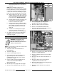
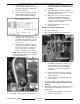
1. Access the descalers (cathodic protectors) as
outlined in REMOVAL AND REPLACEMENT
OF PARTS.
2. Inspect the two descalers hanging in boiler.
NOTE: As descalers erode over time, the diameter
decreases while the length increases.
NOTE: A new descaler is approximately 1 3/8"
diameter and 3 3/4" long at the core.
A. If either descaler has increased to
approximately 6" in length and the core is
breaking apart (pieces falling off), both
descalers should be replaced; or on an
annual basis.
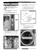
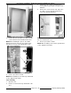
WATER LEVEL PROBE
HOUSING BLOWDOWN
The water level probe housing fills to the same water
level in the boiler; and equalizes to the operating
pressure in the boiler. When the manual ball valve
on the probe housing assembly is opened, water and
steam are blown thru this valve and should be visible
exiting steamer drain. The probe housing blowdown
should be performed in a time frame dependant on
the quality of the local water supply and steamer
usage. In hard water areas or for steamers heavily
used, a more frequent interval should be used. The
blowdown procedure is essential to proper operation
and component life by removing sediment and
scalants that may be lodged in the probe housing.
1. Turn power switch on
and allow boiler to
completely fill (approximately 1" of water visible
in sight glass).
2. Press reset switch to begin heating and allow
boiler to reach operating pressure.
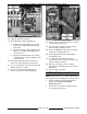
3. Remove left side boiler base panel to access
the manual ball valve.
WARNING: THE STEAMER AND ITS PARTS ARE
HOT. USE CARE WHEN OPERATING, CLEANING
OR SERVICING THE STEAMER. THE BOILER
CONTAINS LIVE STEAM. STAY CLEAR WHEN
OPENING THE VALVE.
4. Open the ball valve for approximately one
minute while under pressure to thoroughly flush
the probes and housing.
5. Close the ball valve and replace left side panel.
6. Press reset switch to resume heating and allow
boiler to reach operating pressure.
7. Steamer is ready for use.
WATER LEVEL CONTROLS
TEST
A build-up of lime scale on or near the water level
sensing probes may cause them to retain moisture
on the probe surface and can give a false reading.
Also, a cracked or damaged insulator may give a
false reading.
These conditions may cause one or more of the
following to occur:
• Boiler no heat
• Boiler no fill
• Boiler overfill
• Boiler no fill and dry fire
NOTE: Dry firing may cause damage to heating
elements or boiler. If this condition is suspected, the
affected components should be inspected.
Main Water Level Control
NOTE: The main water level control is a dual
functioning control that provides low level cut-off
protection and differential water level control
1. Turn power switch on and verify:
A. Low water light is lit (front control panel).
B. HL LED is lit on the water level control
board.
C. Boiler is filling with water.
D. If boiler isn’t filling with water:
1) Verify 120VAC to boiler fill valve.
2) Verify water supply is on and boiler fill
valve isn’t clogged.
2. At the end of the initial fill:
A. Verify approximately 1" of water visible in
sight glass.
B. Verify green ready light is lit (front control
panel).
C. Verify HL LED is not lit and LLCO LED is lit
on the water level control board.
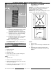
3. Open the ball valve on probe housing assembly
(boiler left side) about half way. This will allow
boiler water to drain slowly and activate a fill
cycle. Do not press the reset switch to start
heating. The next step requires a visual sight
glass measurement that cannot be obtained if
there is boiling action in the vessel.
A. Verify water level in sight glass drops 1/4"
to 3/8" before a fill cycle is initiated. Repeat
at least twice to verify correct fill.
B. If proper fill wasn’t obtained: