
High Efficiency Electric Steamer Service Manual

VHX SERIES STEAMER - SERVICE PROCEDURES AND ADJUSTMENTS
F25154 (February 2004)Page 21 of 48
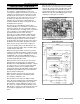
3. To check boiler fill valve:
A. Verify 120VAC to solenoid valve coil.
B. If voltage is correct but valve is not opening
(little or no water flow), turn power switch
off and disconnect power to machine.
1) Remove lead wires from coil and
check for continuity.
2) If no continuity is measured, install a
replacement solenoid valve and check
for proper operation.
3) If continuity is measured, the coil is
good.
C. If voltage is not correct, check main water
level control board as outlined under
WATER LEVEL CONTROLS TEST.
4. To check cold water condenser valve:
NOTE: Valve should energize only during cooking
cycles and at boiler blowdown/drain.
A. Verify 120VAC to solenoid valve coil.
B. If voltage is correct but valve is not opening
(little or no water flow), turn power switch
off and disconnect power to machine.
1) Remove lead wires from coil and
check for continuity.
2) If no continuity is measured, install a
replacement solenoid valve and check
for proper operation.
3) If continuity is measured, the coil is
good. Continue with procedure for
additional valve checks.
C. If voltage is not correct, check cold water
condenser thermostat as outlined under
COLD WATER CONDENSER
THERMOSTAT ADJUSTMENT.
5. To check valve ports for clogs or valve
component malfunction, continue with
procedure for disassembly and inspection of
internal components.
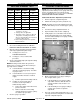
6. Turn water supply off, disconnect water line
from valve body then remove solenoid valve.
7. Remove coil assembly from valve stem
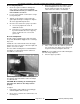
8. Secure the valve body to keep it from turning.
9. Scribe a line on stem nut to valve body for
proper re-tightening then remove stem locking
nut and remove the stem from valve body.
10. All parts are now accessible for inspection and
cleaning.
NOTE: If internal solenoid parts appear to be
damaged or worn, then replace the solenoid valve.
Do not reuse damaged or worn parts. No internal
solenoid parts are available as a service
replacement.
A. Check rubber seal on bottom of plunger.
B. Check plunger spring.
C. Check O-ring in valve body.
D. Check ports in valve body.
11. Reverse procedure to install and check for
proper operation.
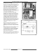
COLD WATER CONDENSER
THERMOSTAT ADJUSTMENT
During a cooking
cycle or boiler blowdown/drain, the
cold water condenser thermostat (N.O.) should
close and energize the cold water condenser
solenoid valve. The water from spray nozzle mixes
with the drain water in the condenser drain box to
reduce drain water temperature and condense
steam vapors.
If excessive steam vapors are seen exiting the drain,
adjust the cold water condenser thermostat as
outlined below.
1. Turn power switch off and allow boiler to
blowdown/drain.
2. Access cold water condenser
thermostat as
outlined under PRESSURE SWITCH
CONTROL BOX COMPONENTS in REMOVAL
AND REPLACEMENT OF PARTS.
3. Turn thermostat shaft fully counterclockwise to
energize the cold water condenser solenoid
valve.
A. Allow cold water to flow until condenser
drain box has completely cooled.
B. Slowly turn thermostat shaft clockwise until
thermostat opens and de-energizes the
solenoid valve. Turn shaft an additional 1/4
turn to prevent the thermostat from closing
near room ambient temperatures.
4. Check for proper operation.