INSTALLATION & OPERATION MANUAL 1024,1036,1048 CHEESEMELTER MODELS 1024C 1024W 1024P 1036C 1036W 1036P 1048C Canadian 1048W Canadian 1048P Canadian ML-103833 ML-103834 ML-103835 ML-103836 ML-103837 ML-103838 ML-103839 ML-126600 ML-103840 ML-126602 ML-103841 ML-126601 Model 1024 In U.S.A.: In Canada: VULCAN-HART COMPANY P.O. BOX 696 LOUISVILLE, KY 40201-0696 TEL.: 502-778-2791 HOBART FOOD EQUIPMENT GROUP CANADA 190 RAILSIDE ROAD NORTH YORK, ONTARIO M3A 1B1 TEL.
–2–
TABLE OF CONTENTS GENERAL............................................................................................................................................. 4 Specifications ........................................................................................................................... 4 INSTALLATION .................................................................................................................................... 5 Unpacking ............................................
OPERATION & INSTALLATION MODELS 1024,1036,1048 CHEESEMELTERS PLEASE KEEP THIS MANUAL FOR FUTURE USE GENERAL Vulcan-Hart Cheesemelters are produced with quality workmanship and material. Proper installation, usage, and maintenance of your cheesemelter will result in many years of satisfactory performance. Thoroughly read this entire manual and carefully follow all of the instructions provided.
INSTALLATION UNPACKING This cheesemelter was inspected before leaving the factory. The transportation company assumes full responsibility for safe delivery upon acceptance of the shipment. Immediately after unpacking, check for possible shipping damage. If the cheesemelter is found to be damaged, save the packaging material and contact the carrier within 7 days of delivery. 1. Unpack cheesemelter and remove all packaging materials.
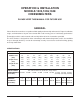
INSTALLATION CODES AND STANDARDS The cheesemelter must be installed in accordance with: In the United States of America: 1. State and local codes. 2. National Electrical Code, ANSI/NFPA-70 (latest edition). Copies may be obtained from The National Fire Protection Association, Batterymarch Park, Quincy, MA 02269. In Canada: 1. Local codes. 2. Canadian Electric Code, CSA C22.1 (latest edition). Copies may be obtained from The Canadian Standard Association, 178 Rexdale Blvd.
–7–
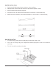
HEATER INSTALLATION 1. Push one end of the heater into one socket as far as it will go. 2. Swing the other end of heater up until it lines up with the opposite socket. 3. Release heater and it will snap into place. 4. Grasp the heater and move it back and forth to ensure that it is centered correctly. 5. Rotate the heater clockwise, then counterclockwise, to ensure that it is seated correctly. RACK INSTALLATION 1. Insert the rack by placing the left pivot point just behind the switch slide. 2.
ELECTRICAL CONNECTIONS WARNING: ELECTRICAL AND GROUNDING CONNECTIONS MUST COMPLY WITH THE APPLICABLE PORTIONS OF THE NATIONAL ELECTRICAL CODE AND/OR OTHER LOCAL ELECTRICAL CODES. WARNING: DISCONNECT ELECTRICAL POWER SUPPLY AND PLACE A TAG AT THE DISCONNECT SWITCH TO INDICATE YOU ARE WORKING ON THE CIRCUIT. Two 1" (25 mm) knockouts are provided at the left rear for conduit installation. The terminal block and grounding lug are located behind the access cover on the left side.
OPERATION WARNING: THE CHEESEMELTER AND ITS PARTS ARE HOT. BE VERY CAREFUL WHEN OPERATING, CLEANING, OR SERVICING THE CHEESEMELTER. 1. Push the main switch to ON. • Pilot lights. • Cooling fan runs. 2. Place the product on the front of the rack. The heaters will automatically come on full power. • If the heaters do not come on full power when the product is placed on the rack: a. Be sure that the product is on the front half of the rack.
TROUBLESHOOTING IF THE CHEESMELTER BLOWS A FUSE OR TRIPS A CIRCUIT BREAKER 1. Check the capacity of the circuit. 2. Contact your local Hobart Food Equipment Group office. IF THE HEATERS DO NOT LIGHT 1. If the pilot light does not come on, and the cooling fan does not run, check for a blown fuse or an open circuit breaker. 2. If the pilot light is lit, and the cooling fan is running, but the heaters do not light, the cheesemelter may be in standby.
NOTES – 12 –
MODE D’EMPLOI SALAMANDRES 1024, 1036 ET 1048 MODÈLES 1024C 1024W 1024P 1036C 1036W 1036P 1048C Canada 1048W Canada 1048P Canada ML-103833 ML-103834 ML-103835 ML-103836 ML-103837 ML-103838 ML-103839 ML-126600 ML-103840 ML-126602 ML-103841 ML-126601 Modèle 1024 F33225B (599) Aux É.-U. : Au Canada : VULCAN-HART COMPANY P.O. BOX 696 LOUISVILLE, KY 40201-0696 TÉL. : (502) 778-2791 GROUPE HOBART CANADA ÉQUIPEMENT ALIMENTAIRE 190 RAILSIDE ROAD NORTH YORK (ONTARIO) M3A 1B1 TÉL.
–2–
TABLE DES MATIÈRES GÉNÉRALITÉS .................................................................................................................................... 4 Caractéristiques ....................................................................................................................... 4 INSTALLATION .................................................................................................................................... 5 Déballage .................................................
Installation et fonctionnement SALAMANDRES 1024, 1036 ET 1048 DOCUMENT À CONSERVER EN CAS DE BESOIN. GÉNÉRALITÉS Les appareils Vulcan sont fabriqués avec le plus grand soin et à partir des meilleurs matériaux. Leur installation, utilisation et entretien appropriés permettront d’en obtenir un rendement optimal pendant de nombreuses années. On recommande de lire ce manuel au complet et de suivre attentivement toutes les instructions.
INSTALLATION DÉBALLAGE Cet appareil a été inspecté avant de quitter l’usine. En acceptant de livrer cette marchandise, le transporteur en assume l’entière responsabilité jusqu’à la livraison. Immédiatement après avoir déballé l’appareil, vérifier s’il n’a pas été endommagé lors du transport. En cas de dommages, conserver le matériel d’emballage et aviser le transporteur dans les sept jours suivant la date de réception. 1. Déballer l’appareil et enlever tout le matériel d’emballage.
CODES D’INSTALLATION ET NORMES L’installation de ces salamandres doit se faire selon les codes suivants : Aux États-Unis : 1. Codes locaux. 2. Norme ANSI/NFPA n° 70 (dernière édition) du National Electrical Code disponible auprès de la National Fire Protection Association, Batterymarch Park, Quincy, MA 02269. Au Canada : 1. Codes locaux. 2. Norme CSA-C22.
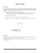
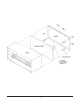
PANNEAU ARRIÈRE ISOLANT APPAREIL TIRE-FONDS VIS DE RETENUE DU PANNEAU ARRIÈRE –7–
INSTALLATION DES ÉLÉMENTS CHAUFFANTS 1. Enfoncer une des extrémités de l’élément chauffant aussi loin que possible dans une douille. 2. Aligner l’autre extrémité avec la douille opposée. 3. Relâcher l’élément chauffant et il s’enclenche en place. 4. Saisir l’élément et lui imprégner un mouvement de va-et-vient pour s’assurer qu’il est bien centré. 5. Tourner l’élément dans le sens des aiguilles d’une montre, puis dans le sens contraire pour s’assurer qu’il est bien en place. INSTALLATION DE LA GRILLE 1.
RACCORDEMENT ÉLECTRIQUE AVERTISSEMENT : LE RACCORDEMENT ÉLECTRIQUE ET LA MISE À LA TERRE DOIVENT ÊTRE CONFORMES AUX NORMES CONCERNÉES DU CODE CANADIEN DE L’ÉLECTRICITÉ OU DE TOUT AUTRE CODE D’ÉLECTRICITÉ EN VIGUEUR. AVERTISSEMENT : COUPER L’ALIMENTATION ÉLECTRIQUE DE L’APPAREIL ET APPOSER UNE ÉTIQUETTE AU DISJONCTEUR POUR AVERTIR QU’UN TECHNICIEN TRAVAILLE SUR LE CIRCUIT. Deux débouchures de 25 mm (1 po) ont été prévues à l’arrière de l’appareil, côté gauche, pour le raccordement électrique.
FONCTIONNEMENT AVERTISSEMENT : LA SALAMANDRE ET SES COMPOSANTS SONT CHAUDS. EXERCER UNE EXTRÊME PRUDENCE LORS DE SON UTILISATION, NETTOYAGE ET ENTRETIEN. 1. Mettre l’interrupteur général sous tension. • Le voyant s’allume. • Le ventilateur se met en marche. 2. Déposer le produit sur la partie avant de la grille. Les éléments chauffants s’allument automatiquement à pleine puissance. • Si les éléments ne s’allument pas à pleine puissance dès qu’on dépose le produit sur la grille: a.
DÉPANNAGE FUSIBLE GRILLÉ OU DISJONCTEUR DÉCLENCHÉ 1. Vérifier la capacité du circuit. 2. Communiquer avec le service de l’entretien Hobart le plus près. LES ÉLÉMENTS CHAUFFANTS REFUSENT DE S’ALLUMER 1. Si le voyant refuse de s’allumer et que le ventilateur ne fonctionne pas, s’assurer qu’aucun fusible n’est grillé ou disjoncteur ouvert. 2. Si le voyant est allumé et le ventilateur fonctionne, il se peut que l’appareil se trouve en mode ATTENTE et que la grille ne comporte aucun produit.
NOTA – 12 –