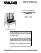
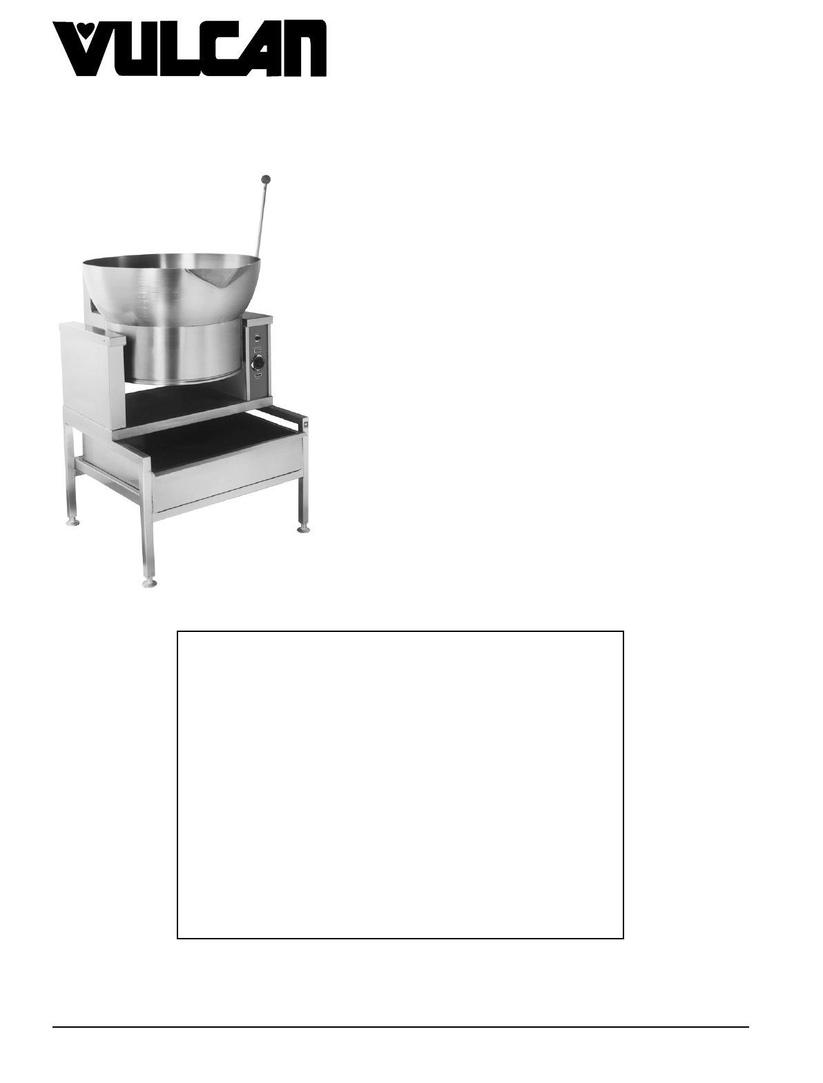
SERVICE MANUAL ROUND COUNTER TOP TILTING BRAISING PANS (16 GALLON) GAS AND ELECTRIC VGCTS16 ML-114827 VECTS16 ML-114825 VGCTS16 SHOWN ON STAND - NOTICE This Manual is prepared for the use of trained Vulcan Service Technicians and should not be used by those not properly qualified. If you have attended a Vulcan Service School for this product, you may be qualified to perform all the procedures described in this manual. This manual is not intended to be all encompassing.
ROUND TILTING BRAISING PANS TABLE OF CONTENTS GENERAL . . . . . . . . . . . . . . . . . . . . . . . . . . . . . . . . . . . . . . . . . . . . . . . . . . . . . . . . . . . . . . . . . . . . . . . . . . . . . Introduction . . . . . . . . . . . . . . . . . . . . . . . . . . . . . . . . . . . . . . . . . . . . . . . . . . . . . . . . . . . . . . . . . . . . . . . . Model Designations . . . . . . . . . . . . . . . . . . . . . . . . . . . . . . . . . . . . . . . . . . . . . . . . . . . . . . . . . . . . . .
ROUND TILTING BRAISING PANS - GENERAL GENERAL INTRODUCTION The Vulcan round tilting braising pan (skillet) is a versatile piece of cooking equipment. It can be used to stew, simmer, sear, pan fry, grill or saute food products under an evenly distributed heating surface. Once the product is fully cooked, the pan can be tilted using the handle to empty the product from the pan. The full capacity of the pan is 16 gallons (60.6 liters) and can be mounted on a counter top or optional stand.
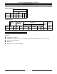
ROUND TILTING BRAISING PANS - GENERAL SPECIFICATIONS Electric Braising Pan AMPERAGE 1 PHASE MODEL VECTS16 TOTAL KW 7.5 3 PHASE 208V 240V 208V 240V 480V 36 31.3 20.8 18.1 9.0 Gas Braising Pan INPUT BTU/HR MODEL VGCTS16 NAT. PROP. 30,000 30,000 LINE PRESSURE (INCHES W.C.) MANIFOLD PRESSURE (INCHES W.C.) NATURAL LOAD (WATTS) PROPANE NAT. PROP. RECOMMEND MIN RECOMMEND MIN MAX 3.5 10.0 7.0 5.0 11.0 11.0 14.0 AMPS (MAX) 120V 60HZ 180 1.
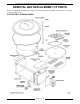
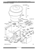
ROUND TILTING BRAISING PANS - REMOVAL AND REPLACEMENT OF PARTS REMOVAL AND REPLACEMENT OF PARTS Refer to the appropriate illustration for component location and identity. Only major components are covered by a replacement procedure.
ROUND TILTING BRAISING PANS - REMOVAL AND REPLACEMENT OF PARTS ILLUSTRATION - GAS MODEL Page 6 of 24
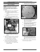
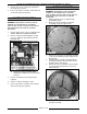
ROUND TILTING BRAISING PANS - REMOVAL AND REPLACEMENT OF PARTS THERMOSTATS (Electric Model) B. Disconnect heater lead wires and mark accordingly for proper replacement. C. Remove the two nuts from mounting stud that secure the insulation pan to the bottom of the braising pan. D. Pull the heater lead wires back through the opening in bearing to allow clearance for the insulation pan to be lifted out. E.
ROUND TILTING BRAISING PANS - REMOVAL AND REPLACEMENT OF PARTS RIGHT AND LEFT CONSOLE COVER WARNING: DISCONNECT THE ELECTRICAL POWER TO THE MACHINE AT THE MAIN CIRCUIT BOX. PLACE A TAG ON THE CIRCUIT BOX INDICATING THE CIRCUIT IS BEING SERVICED. Remove screw at the rear of the cover. 2. Lift up on cover while working it back and forth to free it at the front. Reverse procedure to install. BOTTOM COVER Tilt braising pan forward until it comes to rest on the stop bar. 2.
ROUND TILTING BRAISING PANS - REMOVAL AND REPLACEMENT OF PARTS 4. Remove the screws securing the high limit to the underside of the pan. 5. Reverse procedure to install a new hi limit and check unit for proper operation. HEATING ELEMENTS HEATER CONTACTORS WARNING: DISCONNECT THE ELECTRICAL POWER TO THE MACHINE AT THE MAIN CIRCUIT BOX. PLACE A TAG ON THE CIRCUIT BOX INDICATING THE CIRCUIT IS BEING SERVICED. 1. Remove right console cover as outlined under “RIGHT AND LEFT CONSOLE COVER”. 2.
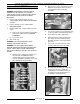
ROUND TILTING BRAISING PANS - REMOVAL AND REPLACEMENT OF PARTS PAN ASSEMBLY B. Remove those same components from the underside of pan and set them aside for re-installing on replacement pan assembly. C. Loosen the nut at the top of the burner that secures the burner to bracket and remove. D. Unscrew the gas orifice and remove. E. Separate the brass union just below the gas swivel connector and unscrew the threaded end of the connector from the pan sleeve. F.
ROUND TILTING BRAISING PANS - REMOVAL AND REPLACEMENT OF PARTS 5. Unbolt the braising pan from the mounting surface or stand. 6. Lay the braising pan on its back to expose the four base plate mounting nuts and bolts. 7. Remove the nuts and carriage bolts on the right side to separate the base plate from the right side support member. BEARINGS WARNING: DISCONNECT THE ELECTRICAL POWER TO THE MACHINE AT THE MAIN CIRCUIT BOX. PLACE A TAG ON THE CIRCUIT BOX INDICATING THE CIRCUIT IS BEING SERVICED. 1.
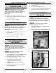
ROUND TILTING BRAISING PANS - SERVICE PROCEDURES AND ADJUSTMENTS SERVICE PROCEDURES AND ADJUSTMENTS WARNING: CERTAIN PROCEDURES IN THIS SECTION REQUIRE ELECTRICAL TEST OR MEASUREMENTS WHILE POWER IS APPLIED TO THE MACHINE. EXERCISE EXTREME CAUTION AT ALL TIMES. IF TEST POINTS ARE NOT EASILY ACCESSIBLE, DISCONNECT POWER, ATTACH TEST EQUIPMENT AND REAPPLY POWER TO TEST. 6. MANIFOLD PRESSURE ADJUSTMENT (Gas Model) WARNING: DISCONNECT THE ELECTRICAL POWER TO THE MACHINE AT THE MAIN CIRCUIT BOX.
ROUND TILTING BRAISING PANS - SERVICE PROCEDURES AND ADJUSTMENTS 2) FLAME SENSE PROBE (Gas Model) WARNING: THE FOLLOWING STEPS REQUIRE POWER TO BE APPLIED TO THE UNIT DURING THE TEST. USE EXTREME CAUTION AT ALL TIMES. 1. Assure proper ground, correct polarity and that the value of incoming voltage is correct. A. Check the flame sense probe micro amp current by disconnecting the fame sense probe lead from the terminal strip and placing a V-O-M in series. 2. B.
ROUND TILTING BRAISING PANS - SERVICE PROCEDURES AND ADJUSTMENTS HOT SURFACE IGNITOR (GAS MODEL) 1. TEMPERATURE CONTROLLER AND POTENTIOMETER TEST (GAS MODEL) Check to see if hot surface ignitor is operating during ignition trial by: A. Visual verification - HSI should be heating up “glowing brightly” to ignite gas. B. Voltage verification - check for 24VAC to HSI termination on the edge connector to ground. WARNING: THE FOLLOWING STEPS REQUIRE POWER TO BE APPLIED TO THE UNIT DURING THE TEST.
ROUND TILTING BRAISING PANS - SERVICE PROCEDURES AND ADJUSTMENTS Potentiometer Perform the following test procedure to verify the potentiometer is functioning properly and to confirm the temperature setting of the dial. A V-O-M connected from TC (-) to the wiper (red) on the potentiometer will read a voltage that corresponds to the set point temperature. Ex. If the set point is 300°F the DC voltage measured at the wiper should be approximately 1.49 volts. 1.
ROUND TILTING BRAISING PANS - ELECTRICAL OPERATION ELECTRICAL OPERATION COMPONENT FUNCTION Heater Contactors . . . . . . . . Controls power to heating elements. (electric models only) Heating Elements (3) . . . . . Heat the braising pan cooking surface. (electric models only) Transformer . . . . . . . . . . . . Provides 24VAC power to ignition control module and HSI. (gas models only) Ignition Module . . . . . . . . . Controls and monitors gas heating.
ROUND TILTING BRAISING PANS - ELECTRICAL OPERATION Gas Model 1. 2. 3. When burner lights, flame sense probe detects flame, HSI deenergizes after an 8.5 second ignition trial time, gas solenoid valve stays open and heating begins. 4) If burner flame is not detected after ignition trial time elapses, then the ignition control module locks out power to the gas solenoid valve.
ROUND TILTING BRAISING PANS - ELECTRICAL OPERATION SCHEMATIC DIAGRAMS Electric Model Page 18 of 24
ROUND TILTING BRAISING PANS - ELECTRICAL OPERATION Gas Model Page 19 of 24
ROUND TILTING BRAISING PANS - ELECTRICAL OPERATION WIRING DIAGRAMS Electric Model (208/240V) Page 20 of 24
ROUND TILTING BRAISING PANS - ELECTRICAL OPERATION Electric Model (480V) Page 21 of 24
ROUND TILTING BRAISING PANS - ELECTRICAL OPERATION Gas Model Page 22 of 24
ROUND TILTING BRAISING PANS - TROUBLESHOOTING TROUBLESHOOTING ALL MODELS WARNING: CERTAIN PROCEDURES IN THIS SECTION REQUIRE ELECTRICAL TESTS OR MEASUREMENTS WHILE POWER IS APPLIED TO THE MACHINE. EXERCISE EXTREME CAUTION AT ALL TIMES. IF TEST POINTS ARE NOT EASILY ACCESSIBLE, DISCONNECT POWER, ATTACH TEST EQUIPMENT AND REAPPLY POWER TO TEST. SYMPTOM Unit will not heat (temperature light off). Pan difficult to tilt. POSSIBLE CAUSES 1. Check incoming voltage. 2.
ROUND TILTING BRAISING PANS - TROUBLESHOOTING GAS MODELS ONLY SYMPTOM Burner won’t light. Burner won’t stay lit. HSI heats up but burner will not light. Form 24643 (MARCH 1999) POSSIBLE CAUSES 1. Gas not on. 2. Pan not down to close limit switch. 3. Unit not properly grounded and/or polarity of incoming power is incorrect. 4. Low incoming gas pressure. 5. Gas solenoid valve malfunction. 6. HSI not operating. See “HOT SURFACE IGNITOR (GAS MODEL)” in “SERVICE PROCEDURES AND ADJUSTMENTS”. 7.