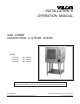
INSTALLATION & OPERATION MANUAL GAS COMBI CONVECTION & STEAM OVENS MODEL VCG10H VCG10F VCG20H ML-126836 ML-126837 ML-126838 Model VCG10H For additional information on Vulcan-Hart or to locate an authorized parts and service provider in your area, visit our website at www.vulcanhart.com VULCAN-HART DIVISION OF ITW FOOD EQUIPMENT GROUP, LLC WWW.VULCANHART.COM P.O. BOX 696, LOUISVILLE, KY 40201-0696 TEL. (502) 778-2791 FORM 31188 Rev. A (Sept.
IMPORTANT FOR YOUR SAFETY THIS MANUAL HAS BEEN PREPARED FOR PERSONNEL QUALIFIED TO INSTALL GAS EQUIPMENT, WHO SHOULD PERFORM THE INITIAL FIELD START-UP AND ADJUSTMENTS OF THE EQUIPMENT COVERED BY THIS MANUAL. POST IN A PROMINENT LOCATION THE INSTRUCTIONS TO BE FOLLOWED IN THE EVENT THE SMELL OF GAS IS DETECTED. THIS INFORMATION CAN BE OBTAINED FROM THE LOCAL GAS SUPPLIER.
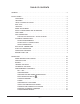
TABLE OF CONTENTS GENERAL . . . . . . . . . . . . . . . . . . . . . . . . . . . . . . . . . . . . . . . . . . . . . . . . . . . . . . . . . . . . . . . . . . 5 INSTALLATION . . . . . . . . . . . . . . . . . . . . . . . . . . . . . . . . . . . . . . . . . . . . . . . . . . . . . . . . . . . . . . 5 UNPACKING . . . . . . . . . . . . . . . . . . . . . . . . . . . . . . . . . . . . . . . . . . . . . . . . . . . . . . . . . . . LOCATION . . . . . . . . . . . . . . . . . . . . . . . . . . . . . . . . . . . . . .
RECALLING A PROGRAM FROM MEMORY . . . . . . . . . . . . . . . . . . . . . . . . . . . . BAKING (CONVECTION BAKING - HOT AIR) . . . . . . . . . . . . . . . . . . . . . . . . . . . CONVECTION BAKING APPLICATIONS . . . . . . . . . . . . . . . . . . . . . . . . . . . . . . . STEAMING . . . . . . . . . . . . . . . . . . . . . . . . . . . . . . . . . . . . . . . . . . . . . . . . . . . . . . . . STEAMING APPLICATIONS . . . . . . . . . . . . . . . . . . . . . . . . . . . . . . . . . . . . . . . . . .
Installation, Operation and Care of GAS COMBI CONVECTION & STEAM OVENS KEEP THIS MANUAL FOR FUTURE USE GENERAL The Vulcan Combi Gas Convection & Steam Ovens are single compartment ovens that provide convection heating, steaming or both. Ovens are sized to accommodate 10 or 20 shelves, Full or Half depth. The bold numbers and letters explain the model number conventions. An atmospheric steam generator is provided for humidification in the oven chamber.
DRIP TRAY Verify that the drip tray is assembled to the bottom of the oven. If it is not, loosen screws under front of oven base and assemble drip tray to bottom of oven. The 20 level ovens have a drip tray that has three segments. LEVELING Caster equipped ovens must be placed on a level floor. For ovens with legs, use a spirit level or pan of water in the bottom of the oven to make sure the oven is level, both front-to-back and side-to-side.
GAS INPUT Burner Input Rating Model VCG10H VCG10F VCG20H Gas Type Gas Pressure Oven Steam Generator Total Convection Steam Natural 67,000 BTU/Hr 40,000 BTU/Hr 107,000 BTU/Hr 3.5" W.C. 3.5" W.C. Propane 69,000 BTU/Hr 40,000 BTU/Hr 109,000 BTU/Hr 10.0" W.C. 10.0" W.C. Natural 85,000 BTU/Hr 45,000 BTU/Hr 130,000 BTU/Hr 3.5" W.C. 3.5" W.C. Propane 85,000 BTU/Hr 45,000 BTU/Hr 130,000 BTU/Hr 10.0" W.C. 10.0" W.C. Natural 70,000 BTU/Hr 58,000 BTU/Hr 128,000 BTU/Hr 3.5" W.C. 3.
PLUMBING CONNECTIONS WARNING: PLUMBING CONNECTIONS MUST COMPLY WITH APPLICABLE SANITARY, SAFETY AND PLUMBING CODES. WATER REQUIREMENTS Supply Pressure Hardness* Silica Total Chlorine pH range Undissolved Solids Water Requirements Proper water quality can improve the taste of the food prepared in the steamer, reduce liming in the steam generator and extend equipment life. Local water conditions vary from one location to another.
ELECTRICAL CONNECTION — Cord Connected Ovens WARNING: ELECTRICAL AND GROUNDING CONNECTIONS MUST COMPLY WITH THE APPLICABLE PORTIONS OF THE NATIONAL ELECTRICAL CODE AND/OR OTHER LOCAL ELECTRICAL CODES. WARNING: THE SUPPLY CORD ON THIS OVEN IS PROVIDED WITH A GROUNDING PLUG. THE OUTLET TO WHICH THIS PLUG IS CONNECTED MUST BE PROPERLY GROUNDED. IF THE RECEPTACLE IS NOT THE PROPER GROUNDING TYPE, CONTACT AN ELECTRICIAN.
OPERATION WARNING: THE OVEN AND ITS PARTS ARE HOT. USE CARE WHEN OPERATING, CLEANING OR SERVICING THE OVEN. THE COOKING COMPARTMENT CONTAINS LIVE STEAM. STAY CLEAR WHEN OPENING DOOR. DOOR OPENING AND CLOSING The oven door is equipped with an electrically powered lock. The oven is delivered with the door latched and slightly open (Fig. 3) and can be opened by firmly pulling the door handle (Fig. 5). Push the door until it connects with the latch but remains slightly open (Fig. 3).
LOADING THE OVEN Open the door. Place the product to be cooked in suitable containers and slide into the racks or place the containers securely on shelves in the oven. When loading a 10 level oven with the landing table (Fig. 6), the bottom frame of the rack should be secured by the rotary lock. Move the loaded landing table to the front of the open oven; secure the landing table to the oven by actuating the locking clamp (or use your body to hold the landing table against the oven).
PROGRAMMABLE CONTROLS ON DOOR ON OFF See Door Opening and Closing, page 10.
ON — After an initial power-up sequence, the control panel indicator lights and the light inside the oven are lit. The actual oven temperature is shown in the Temperature display, – h – – min is in the Time display, and – – is in the Program Number display. The control will now accept commands. The ON button also cancels a manual cooking operation of up to 5 Phases. (Pressing the ON button while the oven is running will open the door. Refer to page 10.
PROBE The Probe Temperature defines the final temperature of the product for any cooking phase. The cooking cycle stops when the product temperature reaches the probe temperature setting. Total Cooking Time is not known or entered when using the probe. COOKING WITH THE PROBE There are two ways to control the oven temperature when using the Probe . . . 1) Setting the Oven Temperature at a constant value. The oven climbs to the set point and the product cooks at that temperature.
TEMPERATURE PROBE APPLICATIONS All Applications are suggested only — prove your own recipes and temperature and time settings. Recommended Final Probe Temperature O F Product Beef Rare Medium Well Done 125 140 180 Lamb 140 – 165 Pork Fresh Smoked 175 140 – 175 Turkey Whole Boneless 185 175 Veal 145 – 165 ENTERING A COOKING PROGRAM HOT AIR STEAM 1.
PROGRAMMING MEMORY Up to 99 Cooking Programs with up to 5 Phases in each program can be keyed-in and stored in Memory. Each program is accessed by its identifying number. Program numbers range from 00 – 98. A pre-defined Clean Cycle Deliming program is also available (refer to page 38). If the numbered Program has not been programmed (or is vacant), the Time displays – h – – min. No Mode or Phase indicator lights are lit. The Temperature displays – – or the current temperature.
To COPY an existing program to a NEW program number — Recall and display the program number that you wish to copy. Press to begin the program. Pause. Press to stop the program. Change the program number to the NEW number. Press until the beep sounds, indicating the program has been copied. To CHANGE a program — With — — in the program number display, the control is in NonProgram mode. Press the key. Program number 00 is displayed.
BAKING (Convection Baking – HOT AIR) Convection Baking involves baking, browning, roasting, etc. without adding steam or moisture to the process. Hot air is fan-circulated to maintain even temperatures throughout the oven. Preheating the oven before loading the product is recommended. Automatic Convection Baking can be set up so the buzzer sounds when the Cooking Time has elapsed or when the product's internal temperature has reached the Probe Temperature set point.
CONVECTION BAKING APPLICATIONS – HOT AIR MODE All Applications are suggested only — prove your own recipes and temperature and time settings.
STEAMING (Steam Mode only) Steam Mode will not begin if cavity temperature is above 212°F (100°C). Steam cooking is used for stewing, poaching and gentle cooking of products cooked in water. Steam flows without pressure into the oven. The fan circulates the steam to all parts of the oven. Allow the steam generator to preheat for 4 to 5 minutes if starting from cold.
STEAMING APPLICATIONS All Applications are suggested only — prove your own recipes and temperature and time settings.
COMBI (Convection Baking with Steam) Combi baking with steam is used for baking, roasting or braising when steam needs to be added to the oven during a convection baking operation. The Steam Factor can be varied by repeat pressing of the Combi key — see Steam Factor in the table below. It is recommended that you preheat the oven.
COMBI APPLICATIONS All Applications are suggested only — prove your own recipes and temperature and time settings. Some applications contain a HOT AIR or Convection Mode phase. Combi Mode is seldom performed as a single phase cooking operation.
EXAMPLE PROGRAM This example shows how to program a two-phase process for cooking Roast Beef and store it as program number 20. The first item in the table on page 23 provides the information: Refer to the menu card example at the bottom of page 25. Phase 1 Phase 2 COMBI 280 OF Steam Factor 50 Convection 425OF 10 minutes Final Internal Temperature: Probe Setting 140 OF Turn the oven ON. Phase 1 Convection HOT AIR Mode by pressing .
MENU CARDS Prep. PROGRAM NUMBER _____________ Menu Item_______________________ MODE FINISH Hot Air Steam Combi (1•, 2•, 3•, 4•, 5•, 6•) TIME Hr. Min. OVEN CONTROL PROBE O F TEMP O F FO Phase 1 Phase 2 Phase 3 Phase 4 Phase 5 PROGRAM NUMBER ______20_______ Menu Item______Roast Beef________ MODE OVEN CONTROL FINISH Hot Air Steam Combi (1•, 2•, 3•, 4•, 5•, 6•) Phase 1 CONVECTION Hot Air Phase 2 COMBI 4• ~ Steam Factor = 50 TIME Hr. Min. PROBE O F 10 Min.
PROGRAM NUMBER _____________ Menu Item_______________________ MODE FINISH Hot Air Steam Combi (1•, 2•, 3•, 4•, 5•, 6•) TIME Hr. Min. PROBE O F OVEN CONTROL TEMP O F FO Phase 1 Phase 2 Phase 3 Phase 4 Phase 5 PROGRAM NUMBER _____________ Menu Item_______________________ MODE FINISH Hot Air Steam Combi (1•, 2•, 3•, 4•, 5•, 6•) Phase 1 Phase 2 Phase 3 Phase 4 Phase 5 – 26 – TIME Hr. Min.
PROGRAM NUMBER _____________ Menu Item_______________________ MODE FINISH Hot Air Steam Combi (1•, 2•, 3•, 4•, 5•, 6•) TIME Hr. Min. PROBE O F OVEN CONTROL TEMP O F FO Phase 1 Phase 2 Phase 3 Phase 4 Phase 5 PROGRAM NUMBER _____________ Menu Item_______________________ MODE FINISH Hot Air Steam Combi (1•, 2•, 3•, 4•, 5•, 6•) Phase 1 Phase 2 Phase 3 Phase 4 Phase 5 – 27 – TIME Hr. Min.
DELUXE MANUAL CONTROL SELECTOR SWITCH • OFF • CONVECTION HOT AIR MODE (Temp.Range 35 – 518°F) • STEAM MODE (Temp. Range 35 – 212°F) • COMBI MODE (Temp. Range 35 – 518°F) • COOL DOWN — Door opens to latched position and fan is on until the set temperature is reached. Fan will come on if thermostat setting is below the actual temperature. • dSCL, Clean Cycle Deliming (page 38) COOKING TIME or PROBE TEMPERATURE • SELECT Cooking Time • DISPLAY Cooking Time Remaining.
ENTERING A MANUAL COOKING OPERATION — Deluxe Control 1. When setting cooking parameters, always select the Mode as the first element in the cooking operation: HOT AIR, STEAM or COMBI. The previous temperature setting used in that Mode is displayed. For Combi Mode, the previous Steam Factor setting is also displayed. After selecting the Mode, the oven begins to heat and maintains the set temperature unless adjusted.
STANDARD MANUAL CONTROL SELECTOR SWITCH HOT AIR • OFF • CONVECTION HOT AIR MODE (Temp.Range: 35 – 518°F) • STEAM MODE (Temp. Range: 35 – 212°F) • COMBI MODE (Temp. Range: 35 – 518°F) • COOL DOWN — Door opens to latched position and fan is on until the set temperature is reached. Fan will come on if thermostat setting is below the actual temperature. • dSCL, Clean Cycle Deliming (page 38) COOKING TIME • SELECT Cooking Time • DISPLAY Cooking Time Remaining.
ENTERING A MANUAL COOKING OPERATION — Standard Control 1. When setting cooking parameters, always select the Mode as the first element in the program: HOT AIR, STEAM or COMBI. The previous temperature setting used in that Mode is displayed. After selecting the Mode, the oven begins to heat and maintains the set temperature unless adjusted.
CLEANING Daily Cleaning Preheat the oven to 130°F and spray a mild detergent solution that does not contain chlorine on the inside surfaces of the oven. A Spray Bottle is provided. Allow the detergent solution to react for 15 minutes. Operate the oven on Steam mode for 15 minutes. Allow the oven to cool; wipe the oven interior with a sponge and warm water. Dry the oven interior with a clean soft cloth. DO NOT use abrasive products.
Complete Cleaning (continued) The Interior Glass Door (Fig. 10) is independently hinged to allow both sides of the glass doors to be cleaned. With the oven door open, pull the Interior Glass Door away from the exterior oven door. The snap-release fasteners should allow the Interior Glass Door to swing free. All four sides of the glass can be cleaned using a cloth and glass cleaner. Alternatively, clean the glass surfaces with soapy water, rinse with clear water and dry with a clean cloth.
CONFIGURATION MODE — PROGRAMMABLE CONTROL This procedure should be performed by a qualified service technician. WARNING: UNPLUG THE ELECTRICAL POWER CORD. Identify the manufacturer(s) of the convection fan motor(s) by inspecting the label on the motor(s) after the rear panel is removed. This information is needed for Steps 10 – 12. Replace rear panel and reconnect electrical power. Some of the procedures in this section are set at the factory and do not need to be re-valued.
8. [ uuu ] is displayed in the TIME display and the maximum steam generator temperature setting is displayed in the TEMPERATURE display. This value can be adjusted depending on the elevation (see Elevation vs. Boiling Temperature Table, below). Press the UP or DOWN arrow keys in the temperature area to increase or decrease the to advance to the next step. numeric value. Press 9000 to Above Sea Level 500 to 1000 to 2000 to 3000 to 4000 to 5000 to 6000 to 7000 to 8000 to 10,000 10,000 to 500 Ft. 1000 Ft.
CONFIGURATION MODE — MANUAL CONTROL (Standard or Deluxe) This procedure should be performed by a qualified service technician. WARNING: UNPLUG THE ELECTRICAL POWER CORD. Identify the manufacturer(s) of the convection fan motor(s) by inspecting the label on the motor(s) after the rear panel is removed. This information is needed for Steps 9 – 11. Replace rear panel and reconnect electrical power. Some of the procedures in this section are set at the factory and do not need to be re-valued.
7. [ uuuu ] is displayed in the TIME display and the maximum steam generator temperature setting is displayed in the TEMPERATURE display. This value must be adjusted for the elevation (see Elevation vs. Boiling Temperature Table, below). Rotate the adjustment knob clockwise to increase or counterclockwise to decrease the numeric TIME to advance to the next step. value.
MAINTENANCE WARNING: THE OVEN AND ITS PARTS ARE HOT. USE CARE WHEN OPERATING, CLEANING OR SERVICING THE OVEN. THE COOKING COMPARTMENT CONTAINS LIVE STEAM. STAY CLEAR WHEN OPENING DOOR. CLEAN CYCLE DELIMING PROCEDURE • With the Programmable Control, select the Clean Cycle [Program Number 00 and or Program ]. [ CC ] will display as the Program Number, [ dSCL ] will display in the Number 98 and Temperature Display. Push Start Stop. The indicator light in the Start Stop key will light.
TROUBLESHOOTING SYMPTOM SUGGESTED CORRECTIVE ACTION Steam button, Combi button and Steam Factor lights are all flashing. Oven works in Hot Air mode but not in Steam or Combi modes. The treated water supply valve is off. Open the water supply valve. Turn oven off and then back on. Allow the steam generator to preheat. The Air Intake Trouble Indicator Light is lit. The air supply to the convection burner is blocked. Press the left Reset button.
SERVICE ADJUSTMENTS Buzzer loudness can be adjusted by your service technician. SERVICE AND PARTS INFORMATION To obtain service and parts information concerning this oven, contact the Vulcan Hart Service Agency in your area (refer to the listing supplied with the oven), or contact the Vulcan-Hart Service Department at the address or phone number shown on the front cover of this manual. Parts and service manuals are also available at WWW.VULCANHART.COM FORM 31188 Rev. A (Sept. 2004) – 40 – PRINTED IN U.