
User Manual


— 12 —
F35628 (10-04)
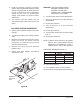
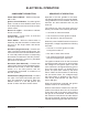
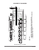
COMPONENT DESCRIPTION
Power Switch ON/OFF – Switch turns power
ON or OFF.
Ignition Control Module – Provides ignition
spark. Turned on when ON/OFF switch is set
to the ON position and turned off when flame
switch closes.
Burner On Lights – Illuminates to indicate
burner is turned on.
Thermostats – Turns burner on and sets
operating temperature.
Flame Switch – When the flame switch is
heated by the pilot the switch contacts close
and turn on the single and/or dual burner
solenoids.
Gas Valve (Single Solenoid) – Contains one
valve. The valve controls a single burner. The
solenoid is turned on when the ON/OFF switch
is in the ON position and the corresponding
thermostat is rotated out of the OFF position.
When the solenoid is turned on (operated)
gas flows to the burners.
Gas Valve (Dual Solenoid) – Contains two
valves. Each valve controls a separate burner.
Solenoids are turned on when the ON/OFF
switch is in the ON position and the
corresponding thermostat is rotated out of
the OFF position.
Pilot Gas Valve (Single Solenoid) – Contains
one valve. The valve controls the gas to the
pilot. The solenoid is turned on when the
ON/OFF switch is in the ON position and
turned off when the flame switch closes.
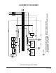
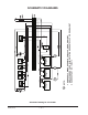
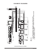
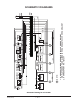
SEQUENCE OF OPERATION
Operation of all size griddles is the same.
The following discussion is for the 48” griddle.
This griddle has four thermostats, two flame
switches, two dual solenoids and one pilot
solenoid.
The neutral wire from the power source is
directly connected to the following terminals:
• A terminal on each thermostat
• The N terminal on each ignition module
• One terminal on the pilot solenoid
When the power ON/OFF switch is set to the
ON position, voltage is applied to the following
terminals:
• Terminal L1 on each ignition module
turning the module on
• One side of each flame switch
• The remaining terminal on the pilot
solenoid energizing the solenoid
The ignition module which is now connected
across the power lines turns on and provides
the voltage for the ignition spark. The pilot
valve solenoid is energized allowing gas to
flow to the pilot where it is ignited by the
spark. The pilot flame heats up the flame
switch. When the flame switch is sufficiently
hot, the switch closes. The voltage through
the flame switch is applied to one side of
each burner solenoid and one side of the
burner ON light.
When the pilot flame is sensed, the ignition
module will shut off automatically.
When a thermostat is rotated out of the OFF
position the neutral return wire is connected
to the other side of the burner light causing
the light to be illuminated. At the same time
the neutral is connected to the other side of
the burner solenoid causing the solenoid to
operate and allowing gas to flow to the burner.
ELECTRICAL OPERATION