
User Manual

— 7 —
F35628 (10-04)
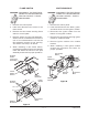
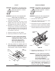
FLAME SWITCH
WARNING: DISCONNECT THE ELECTRICAL
POWER TO THE MACHINE AND
FOLLOW LOCKOUT / TAGOUT
PROCEDURES.
1. Remove the control panel.
2. Label and disconnect the wires to the
flame switch.
3. Remove the two screws securing flame
switch to control plate.
4. Remove sensor from the pilot assembly.
Sensor can be accessed from the front of
unit or from underneath the unit via the
pilot assembly access cut out opening.
The sensor is a snap in fit device.
5. When installing a new flame switch,
reverse the procedure. Be sure to carefully
route and attach the sensor to the pilot
assembly and check for proper operation.
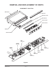
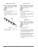
Figure F
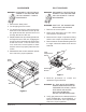
IGNITOR MODULE
WARNING: DISCONNECT THE ELECTRICAL
POWER TO THE MACHINE AND
FOLLOW LOCKOUT / TAGOUT
PROCEDURES.
1. Remove the control panel.
2. Label and disconnect the black, green,
and white wires from the ignitor module.
3. Disconnect the ignitor cable from the
bottom of the ignitor module.
4. Remove the two screws securing ignitor
module to module bracket.
5. Remove ignitor module from module
bracket.
6. When installing a new ignitor module
reverse the procedure and check for
proper operation.
Figure G
Flame
Switch
Sensor
Remove
Probe
From Pilot
Assembly
Remove
Screws
Module
Bracket
Disconnect
Wires
Remove
Screw
Module
Bracket
Disconnect
Wires
Disconnect
Wire
Ignitor
Electrode
Ignitor
Module
Flame
Switch