INSTALLATION & OPERATION MANUAL 900RX Heavy Duty Gas Griddles MODEL MLS 924RX ML-135309-924RX 936RX ML-135310-936RX 948RX ML-135311-948RX 960RX ML-135312-960RX 972RX ML-135313-972RX www.vulcanhart.com 936RX ITW Food Equipment Group, LLC 3600 North Point Blvd. Baltimore, MD 21222 RETAIN THIS MANUAL FOR FUTURE USE FORM F-36968 (rev.
IMPORTANT FOR YOUR SAFETY THIS MANUAL HAS BEEN PREPARED FOR PERSONNEL QUALIFIED TO INSTALL GAS EQUIPMENT, WHO SHOULD PERFORM THE INITIAL FIELD START-UP AND ADJUSTMENTS OF THE EQUIPMENT COVERED BY THIS MANUAL. POST IN A PROMINENT LOCATION THE INSTRUCTIONS TO BE FOLLOWED IN THE EVENT THE SMELL OF GAS IS DETECTED. THIS INFORMATION CAN BE OBTAINED FROM THE LOCAL GAS SUPPLIER.
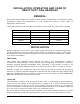
INSTALLATION, OPERATION AND CARE OF HEAVY DUTY GAS GRIDDLES GENERAL Heavy Duty Gas Griddles are produced with quality workmanship and materials. Proper installation, usage and maintenance of your griddle will result in many years of satisfactory performance.
This griddle is Design Certified for installation on a non-combustible counter with 4” legs, or combustible floor with 25” high stand. INSTALLATION CLEARANCES Back: Right Left Side COMBUSTIBLE CONSTRUCTION NON-COMBUSTIBLE CONSTRUCTION 6” 6” 6” 0” 0” 0” INSTALLATION CODES AND STANDARDS The griddle must be installed in accordance with: In the United States of America: 1. State and local codes. 2. National Fuel Gas Code, ANSI-Z223.1/NFPA #54 (latest edition).
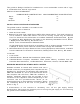
Casters are only supplied on a griddle stand. If the griddle is moved for any reason the griddle should be re-leveled (see LEVELING in this manual). FLUE CONNECTIONS Do not obstruct the flow of flue gases from the flue, located at the rear of the griddle. It is recommended that flue gases be ventilated to the outside of the building through a ventilation system installed by qualified personnel.
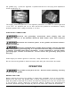
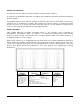
the griddle (Fig. 1) and the regulator is positioned with the vent plug and adjustment screw upright (Fig. 2). Fig. 1 Fig. 2 The supply pressure (upstream of the regulator) should be 7-9” W.C. for natural gas and 11-12” W.C. for propane gas. At no time should the griddle be connected to supply pressure greater than ½ psig (3.45 kPa) or 14” W.C.
SEASONING THE GRIDDLE Season the griddle to avoid possible surface corrosion before first use, and after every cleaning. Heat griddle to a low temperature (300-350°F) and apply a small amount of cooking oil – about one ounce per square foot of surface. Use a soft lint-free cloth to spread the oil over the entire griddle surface to create a thin film. Wipe off any excess oil with a cloth. Repeat the procedure until the griddle has a slick, mirror-like finish.
900RX PILOT LIGHTING PROCEDURE 1. Turn all thermostats to the OFF position. Wait 5 minutes to allow any gas that may have accumulated in the burner compartment to escape. 2. Turn on the main gas shut-off valve. 3. Push the power switches to ON. The switches will illuminate and you will hear a “clicking” sound. 4. Depress and hold the red buttons on the pilot safety valves while the electric igniters light the corresponding pilots. You will have to monitor the pilot burners through the pilot sight holes.
USING THE GRIDDLE To preheat, turn the burners on about 20-25 minutes before cooking. A uniform and systematic approach to loading the griddle will produce the most consistent product results. The griddle plate is steel, but the surface is relatively soft and can be scored or dented by careless use of a spatula or scraper. Be careful not to dent, scratch, or gouge the plate surface.
CLEANING THE GRIDDLE Empty the grease drawer as needed throughout the day and regularly clean at least once daily. Clean the griddle regularly. A clean griddle always looks better, lasts longer and performs better. To produce evenly cooked, perfectly browned griddle products keep the griddle plate clean and free of carbonized grease. Carbonized grease on the surface hinders the transfer of heat from the griddle surface to the food, resulting in spotty browning and loss of cooking efficiency.
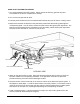
ADJUSTMENTS CALIBRATION 1. Each thermostat controls a 12” zone of the griddle. Using a Surface Probe temperature measurement device, observe the temperatures at the center points of the cooking zones. These points are located by starting 6” from the side splash (left or right) and every 12” across the width of the griddle, with all points located 12” back from the front edge of the griddle plate. NOTE: Use of infrared thermometers is not recommended.
LEVELING The griddle must be level (side-to-side and front-to-back) during operation to ensure proper performance. Improper leveling can result in uneven temperature distribution, cold spots, and possibly damage electrical components. 1. Place a level on the griddle. 2. Adjust legs by turning the bullet feet at the bottom of each leg. Using pliers or a crescent wrench, turn the feet counter-clockwise to increase height, and clockwise to decrease height until leveling is achieved.
SERVICE AND PARTS INFORMATION Contact the Service Agency in your area to obtain service and parts information. For a complete listing of Service and Parts depots refer to or www.vulcanhart.com. When calling for service the following information should be available from the appliance serial plate: Model Number, Serial Number and Gas Type. ACCESSORIES STANDS The griddle has an optional 24” high by 30” deep by 24”, 36”, 48”, 60” stainless steel stand with casters or flanged legs.
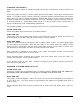
TROUBLESHOOTING PROBLEM POSSIBLE CAUSES Heat does not come on when the thermostat is turned on 1. Problem with thermostat. (Call for service) 2. Pilot burner not lit. (Call for service) 3. Problem with gas valve (Call for service) Pilot burner will not light 1. 2. 3. 4. 5. 6. Manual gas valve not turned on. Obstructed pilot orifice. (Call for service) Pilot gas turned off at pilot. (Call for service) Problem with pilot safety valve. (Call for service) Problem with thermocouple.