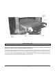
SERVICE MANUAL HEAVY DUTY GAS BROILER MODELS GHCB40 GHCB44 GHMCB44 HCB1 HCB2(B) IR1 IR2(B) GHIR44 ML-052211 ML-052213 ML-052214 ML-052202 ML-052208 ML-052200 ML-052201 ML-052210 GHCB40 SHOWN – NOTICE – This Manual is prepared for the use of trained Vulcan Service Technicians and should not be used by those not properly qualified. If you have attended a Vulcan Service School for this product, you may be qualified to perform all the procedures described in this manual.
TABLE OF CONTENTS GENERAL ................................................................................................................................................................ Introduction ................................................................................................................................................. Installation and Operation ............................................................................................................................ Cleaning .....
Gas Valves, Tubing, Thermostats, Regulators and Solenoids .................................................................... Burner Manifold Assembly (GHCB40) ................................................................................................. Burner Manifold Assembly (GHIR44) .................................................................................................. Oven Pilot Valve (GHCB40) ..............................................................................................
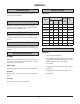
GENERAL SPECIFICATIONS INTRODUCTION Gas Data This service manual was specially written for the Heavy Duty Gas Broilers. Dimensions Model INSTALLATION AND OPERATION Detailed installation and operation instructions are included in the Installation and Operation Manual which is sent with each Broiler. CLEANING Detailed cleaning instructions are included in the Installation and Operation Manual for the appropriate model. LIGHTING PILOT Width No.
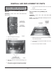
IMPORTANT STOP BOLTS MUST BE IN POSITION FOR SAFE OPERATION OF GRID. IF DAMAGED OR MISSING, REPLACE AT ONCE. DO NOT OPERATE GRID WITHOUT BOLTS. Two (2) broiler grid 1/4-20 stop bolts and nuts are supplied with each broiler grid to ensure that the grid is not accidentally pulled completely from the broil section while hot. One (1) stop bolt and nut are mounted to the grid carriage RT. and LT. HD. side member through a 0.281 diameter hole directly in front of the grid stop tab.
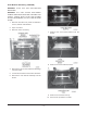
REMOVAL AND REPLACEMENT OF PARTS 5. Lift and remove the burner box cover from the broiler. COVERS, PANELS AND HANDLES 6. Reverse the procedure to install. Burner Box Cover (GHCB40, GHCB44, GHIR44) Burner Shield Cover [HCB2(B), IR1, IR2(B)] WARNING: SHUT OFF THE GAS BEFORE SERVICING. WARNING: SHUT OFF THE GAS BEFORE SERVICING. NOTE: The models HCB2(B) and IR2(B) have two burner shield covers. 1. Open the augratin oven door. 1. Remove the two screws from the burner shield cover and the broiler. 2.
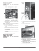
Manifold Cover Assembly (GHCB40 & GHIR44) WARNING: SHUT OFF THE GAS BEFORE SERVICING. 1. Remove the grease tray from the broiler (GHCB40 only). 1. Loosen the mounting screw in each burner knob. NOTE: The GHIR44 manifold cover assembly has a chain to protect switch wiring. 2. Remove the burner knob. 2. Loosen the mounting screw in each burner knob. 3. Remove the two burner knobs from the broiler. 4. Remove the two screws from the manifold cover assembly. 5.
Control Panel Cover (GHCB40) 4. Remove the bolt and the control panel cover from the broiler. 1. Remove the manifold cover assembly as outlined in Manifold Cover Assembly. 5. Reverse the procedure to install. Lower Front Panel (GHCB40) 1. Grasp the bottom of the lower front panel. 2. Pull the lower front panel out to remove it from the broiler. 2. Loosen the retaining screw and remove the burner knob from the broiler. 3. Reverse the procedure to install. 3.
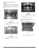
Oven Bottom Assembly (GHCB40) WARNING: SHUT OFF THE GAS BEFORE SERVICING. WARNING: ALL GAS JOINTS DISTURBED DURING SERVICING MUST BE CHECKED FOR LEAKS. CHECK WITH SOAP AND WATER SOLUTION (BUBBLES). DO NOT USE AN OPEN FLAME. 1. Remove the lower front panel as outlined in Covers, Panels and Handles. 2. Open oven door. 3. Remove rack if necessary. 7. Remove the oven bottom baffle from the broiler. 8. Remove the oven insulation sheet. 4. Remove the two screws and brass bushings from the broiler. 5.
Augratin Oven Bottom Assembly (GHCB40) WARNING: ALL GAS JOINTS DISTURED DURING SERVICING MUST BE CHECKED FOR LEAKS. CHECK WITH SOAP AND WATER SOLUTION (BUBBLES). DO NOT USE AN OPEN FLAME. 3. Remove the augratin oven bottom baffle from the broiler. 4. Reverse the procedure to install. NOTE: When installing bottom assembly, angle metal should be at the rear of the oven. Oven Door Handle (GHCB40) 1. Remove the four screws and brass bushings from the broiler. 1. Remove the caps from the oven door. 2.
GRID CARRIAGE ASSEMBLY (ALL MODELS) WARNING: SHUT OFF THE GAS BEFORE SERVICING. WARNING: ALL GAS JOINTS DISTURBED DURING SERVICING MUST BE CHECKED FOR LEAKS. CHECK WITH SOAP AND WATER SOLUTION (BUBBLES). DO NOT USE AN OPEN FLAME. WARNING: SPRING UNDER TENSION. AND HOOK BOLT ARE 1. Remove the broiler grid tray as outlined in Broiler Grid Tray. 2. Remove two screws and the oven door handle from the oven door. 2. Remove cover manifold cover assembly as outlined in Covers, Panels and Handles. 3.
BURNER CERAMICS (GHCB40) WARNING: SHUT OFF THE GAS BEFORE SERVICING. NOTE: Lower broiler pan for easier access. 1. Allow the burner ceramics to cool. 4. Remove the grid handle from the grid arm lifting assembly. 5. Remove two bolts, six washers and two nuts from the grid arm lifting assembly and the grid carriage assembly. 6. Remove the grid arm lifting assembly from the grid carriage assembly and the broiler. 2. Carefully push up on the side and center ceramics to remove from the broiler. 3.
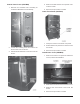
GHIR44 BURNER ASSEMBLY WARNING: SHUT OFF THE GAS BEFORE SERVICING. GHCB40 & HCB2(B) 1. Allow the burner assembly to cool. WARNING: SHUT OFF THE GAS BEFORE SERVICING. 1. Remove the burner ceramics as outlined under Burner Ceramics. 2. Remove burner box cover as outlined in Controls, Panels and Handles. 2. Lift the rear of the burner assembly off the alignment pins. 3. Carefully move the burner assembly to the rear of the broiler and then remove burner from the broiler. 3.
HEAT SHIELD (GHIR44) WARNING: SHUT OFF THE GAS BEFORE SERVICING. 1. Remove burner assemblies as outlined in Burner Assembly. 4. Remove the pilot elbow nozzle from submanifold assembly. 5. Reverse the procedure to install. SUB-MANIFOLD ASSEMBLY GHCB40 2. Remove the cotter pin from the shaft of the heat shield. WARNING: SHUT OFF THE GAS BEFORE SERVICING. 3. Remove the heat shield from the broiler. WARNING: ALL GAS JOINTS DISTURBED DURING SERVICING MUST BE CHECKED FOR LEAKS.
3. Remove the two nuts and washers from the sub-manifold and the bracket. 4. Disconnect the sub-manifold from the elbow. 5. Remove the sub-manifold from the broiler. 6. Reverse the procedures to install. BURNER SUB-MANIFOLD (GHIR44) WARNING: SHUT OFF THE GAS BEFORE SERVICING. WARNING: ALL GAS JOINTS DISTURBED DURING SERVICING MUST BE CHECKED FOR LEAKS. CHECK WITH SOAP AND WATER SOLUTION (BUBBLES). DO NOT USE AN OPEN FLAME. NOTE: These procedures apply to the left and right side burner subassemblies. 4.
5. Loosen the two nuts on the burner submanifold. 6. Remove the burner sub-manifold from the broiler. 3. Disconnect the four pilot burner nozzles from the pilot manifold. 7. Reverse the procedure to install. PILOT MANIFOLD (GHIR44) WARNING: SHUT OFF THE GAS BEFORE SERVICING. WARNING: ALL GAS JOINTS DISTURBED DURING SERVICING MUST BE CHECKED FOR LEAKS. CHECK WITH SOAP AND WATER SOLUTION (BUBBLES). DO NOT USE AN OPEN FLAME. 1. Remove the burner box cover as outlined in Covers, Panels and Handles. 4.
OVEN BURNER ASSEMBLY (GHCB40) WARNING: SHUT OFF THE GAS BEFORE SERVICING. WARNING: ALL GAS JOINTS DISTURBED DURING SERVICING MUST BE CHECKED FOR LEAKS. CHECK WITH SOAP AND WATER SOLUTION (BUBBLES). DO NOT USE AN OPEN FLAME. 1. Remove the oven bottom assembly as outlined in Covers, Panels and Handles. 3. Remove the two screws and plate from the broiler. 2. Lift and remove the oven burner assembly from the broiler. 3. Reverse the procedure to install. 4.
GAS VALVES, TUBING, THERMOSTATS, REGULATORS AND SOLENOIDS Burner Manifold Assembly (GHCB40) WARNING: SHUT OFF THE GAS BEFORE SERVICING. WARNING: ALL GAS JOINTS DISTURBED DURING SERVICING MUST BE CHECKED FOR LEAKS. CHECK WITH SOAP AND WATER SOLUTION (BUBBLES). DO NOT USE AN OPEN FLAME. 1. Remove the manifold cover assembly as outlined in Covers, Panels and Handles. 6. Disconnect the oven gas supply tube from the burner manifold assembly.
Burner Manifold Assembly (GHIR44) Oven Pilot Valve (GHCB40) WARNING: SHUT OFF THE GAS BEFORE SERVICING. WARNING: SHUT OFF THE GAS BEFORE SERVICING. WARNING: ALL GAS JOINTS DISTURBED DURING SERVICING MUST BE CHECKED FOR LEAKS. CHECK WITH SOAP AND WATER SOLUTION (BUBBLES). DO NOT USE AN OPEN FLAME. WARNING: ALL GAS JOINTS DISTURBED DURING SERVICING MUST BE CHECKED FOR LEAKS. CHECK WITH SOAP AND WATER SOLUTION (BUBBLES). DO NOT USE AN OPEN FLAME. 1.
2. Disconnect the oven burner valve from the oven gas supply tube and the union. 3. Disconnect the pilot valve tubing from the pilot outage protection valve. 3. Reverse the procedure to install. 4. Remove the oven bottom assembly as outlined in Covers, Panels and Handles. Pilot Outage Protection Valve (GHCB40) WARNING: SHUT OFF THE GAS BEFORE SERVICING. WARNING: ALL GAS JOINTS DISTURBED DURING SERVICING MUST BE CHECKED FOR LEAKS. CHECK WITH SOAP AND WATER SOLUTION (BUBBLES). DO NOT USE AN OPEN FLAME. 1.
6. Remove the two bolts from the pilot outage protection valve and the bracket. 3. Disconnect the thermostat from the pilot outage protection valve and from the oven burner tubing. 7. Disconnect the pilot outage protection valve from the union and the thermostat. 8. Remove the pilot outage protection valve and the ignitor wire from the broiler. 9. Reverse the procedure to install. Thermostat (GHCB40) WARNING: SHUT OFF THE GAS BEFORE SERVICING.
Oven Burner Nozzle (GHCB40) Burner Valve [(IR2(B) and HCB2(B)] WARNING: SHUT OFF THE GAS BEFORE SERVICING. WARNING: SHUT OFF THE GAS BEFORE SERVICING. WARNING: ALL GAS JOINTS DISTURBED DURING SERVICING MUST BE CHECKED FOR LEAKS. CHECK WITH SOAP AND WATER SOLUTION (BUBBLES). DO NOT USE AN OPEN FLAME. WARNING: ALL GAS JOINTS DISTURBED DURING SERVICING MUST BE CHECKED FOR LEAKS. CHECK WITH SOAP AND WATER SOLUTION (BUBBLES). DO NOT USE AN OPEN FLAME. 1.
Burner Valve (GHIR44) Regulator (GHIR44) WARNING: DISCONNECT THE ELECTRICAL POWER TO THE MACHINE AND FOLLOW LOCKOUT / TAGOUT PROCEDURES. WARNING: DISCONNECT THE ELECTRICAL POWER TO THE MACHINE AND FOLLOW LOCKOUT / TAGOUT PROCEDURES. WARNING: SHUT OFF THE GAS BEFORE SERVICING. WARNING: SHUT OFF THE GAS BEFORE SERVICING. WARNING: ALL GAS JOINTS DISTURBED DURING SERVICING MUST BE CHECKED FOR LEAKS. CHECK WITH SOAP AND WATER SOLUTION (BUBBLES). DO NOT USE AN OPEN FLAME.
Regulator [HCB2(B)] Solenoid (GHIR44) WARNING: SHUT OFF THE GAS BEFORE SERVICING. WARNING: DISCONNECT THE ELECTRICAL POWER TO THE MACHINE AND FOLLOW LOCKOUT / TAGOUT PROCEDURES. WARNING: ALL GAS JOINTS DISTURBED DURING SERVICING MUST BE CHECKED FOR LEAKS. CHECK WITH SOAP AND WATER SOLUTION (BUBBLES). DO NOT USE AN OPEN FLAME. WARNING: SHUT OFF THE GAS BEFORE SERVICING. WARNING: ALL GAS JOINTS DISTURBED DURING SERVICING MUST BE CHECKED FOR LEAKS. CHECK WITH SOAP AND WATER SOLUTION (BUBBLES).
Lower LEVER ARM ASSEMBLY (ALL MODELS) WARNING: SHUT OFF THE GAS BEFORE SERVICING. Upper WARNING: ALL GAS JOINTS DISTURBED DURING SERVICING MUST BE CHECKED FOR LEAKS. CHECK WITH SOAP AND WATER SOLUTION (BUBBLES). DO NOT USE AN OPEN FLAME. WARNING: SHUT OFF THE GAS BEFORE SERVICING. WARNING: ALL GAS JOINTS DISTURBED DURING SERVICING MUST BE CHECKED FOR LEAKS. CHECK WITH SOAP AND WATER SOLUTION (BUBBLES). DO NOT USE AN OPEN FLAME. 1.
2. Remove the four screws from the bracket and blower and motor. 3. Move the bracket away from the blower and motor. 3. Remove the two cotter pins and washers from the lower lever arm assembly. 4. Remove the lower lever arm assembly from the two brackets. 5. Reverse the procedure to install. BLOWER AND MOTOR GHIR44 WARNING: SHUT OFF THE GAS BEFORE SERVICING. WARNING: DISCONNECT THE ELECTRICAL POWER TO THE MACHINE AND FOLLOW LOCKOUT / TAGOUT PROCEDURES. 4.
Blower Switch (GHIR44) WARNING: DISCONNECT THE ELECTRICAL POWER TO THE MACHINE AND FOLLOW LOCKOUT / TAGOUT PROCEDURES. WARNING: SHUT OFF THE GAS BEFORE SERVICING. 1. Remove the manifold cover assembly as outlined in Covers, Panels and Handles. 8. Disconnect the electrical wires. 9. Remove the blower and motor from the broiler. 10. Reverse the procedure to install. IR1 and IR2(B) WARNING: DISCONNECT THE ELECTRICAL POWER TO THE MACHINE AND FOLLOW LOCKOUT / TAGOUT PROCEDURES. 2.
Light (GHIR44) WARNING: DISCONNECT THE ELECTRICAL POWER TO THE MACHINE AND FOLLOW LOCKOUT / TAGOUT PROCEDURES. WARNING: SHUT OFF THE GAS BEFORE SERVICING. 1. Remove the manifold cover assembly as outlined in Covers, Panels and Handles. 2. Note the location and connection of the electrical wires. 3. Disconnect the electrical wires from the light. 4. Reverse the procedure to install.
PILOT ADJUSTMENT (ALL MODELS) 1. Light the pilot as outlined under Lighting Pilot in the Installation and Operation manual for the appropriate model. 2. Locate the pilot adjustment screw on the supply end of pilot manifold pipe. 3. With a flat blade screwdriver, turn the pilot adjustment screw counterclockwise to increase or clockwise to decrease gas flow. The flame should only be high enough to ignite the burner in less than 4 seconds. 4. Turn the burner on .
BURNER SERVICE (ALL MODELS) WARNING: SHUT OFF THE GAS BEFORE SERVICING THE OVEN. If the burner ports become obstructed or the burner cracks, the burner will not operate properly. 1. Remove burner(s) as outlined under Burner Assemblies Section of this manual. 2. Check burner(s) for: A. Obstruction in port holes. 1) Soak the burner(s) in warm, soapy water. If this does not solve the problem, the obstruction may be removed by carefully inserting, by hand, the proper size drill bit.
TROUBLESHOOTING SYMPTOMS POSSIBLE CAUSES Uneven heating, sides burning. A) Temperature too low. B) Improper operation of broiler. C) Fluctuating gas pressure. Too much top heat. A) B) C) D) Uneven heat front to back. A) Appliance not level front to back. Dried out products. A) Broiling time too long or product too close to the burner. B) Gas pressure too high or orifice too large. Pilot outage. A) Pilot flame too low. B) Restriction in pilot orifice. Pilot will not light.
FORM 35608 (Aug. 2003) – 32 – PRINTED IN U.S.A.