SERVICE MANUAL SG4 & SG6 SERIES FULL SIZE GAS CONVECTION OVENS MODELS SG4D SG4C SG6D SG6C ML-114875 ML-114876 ML-114877 ML-114878 Model SG4D - NOTICE This manual is prepared for the use of trained Vulcan Service Technicians and should not be used by those not properly qualified. If you have attended a Vulcan Service School for this product, you may be qualified to perform all the procedures described in this manual. This manual is not intended to be all encompassing.
© VULCAN-HART, 2008 –2–
TABLE OF CONTENTS GENERAL .............................................................................................................................................................. 5 Introduction ............................................................................................................................................... Installation ................................................................................................................................................
TABLE OF CONTENTS (Cont.) Computer Controller (SG4C/SG6C) ......................................................................................................... 23 Operation ........................................................................................................................................... 23 Setup Mode ....................................................................................................................................... 23 Probe Test ...............................
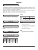
GENERAL INTRODUCTION Procedures in this manual will apply to all models unless specified. Pictures and illustrations can be of any model unless the picture or illustration needs to be model specific. All models are equipped with a two-speed 1/2 HP electric motor, porcelain interior and two 30,000 BTU/hr burners as standard equipment. A power level control permits variable burner input from 15,0000 BTU/hr to 60,000 BTU/hr.
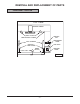
REMOVAL AND REPLACEMENT OF PARTS COMPONENT LOCATION TOP VIEW BLOWER MOTOR OVEN LIGHTS COOLING FAN TEMPERATURE PROBE GAS BURNERS COMPONENT PANEL IGNITER & FLAME SENSE GAS VALVE HIGH LIMIT DOOR SWITCH CONTROL PANEL PL-56044 –6–
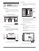
Control Panel COVERS AND PANELS 1. Remove three screws on the right side which secure the control panel. Pull the panel away from the oven. Disconnect the electrical power to the machine and follow lockout / tagout procedures. CONTROL PANEL Top Front Cover MASTER SWITC H OVEN COOL 1. The top front cover is secured with four screws, two on each side of cover. Remove these screws, then remove the cover from the oven.
CONTROL PANEL COMPONENTS MAS TER MASTER SWITCH SWIT CH OVE N COO L ON OFF O N / H E AT I N D I C ATO R LIGHTS NO IGNITION LIGHT THE RMO STAT COMPUTER CONTROLLER T E M P E R AT U R E C O N T RO L L E R ( T H E R M O S TAT ) 0 55 50 45 40 35 30 25 POW ER LE VEL P OW E R C O N T RO L TIME R NO IGNITION LIGHT TIMER 0 55 50 45 40 35 30 POWER SWITCH 25 FAN FA N S P E E D SWITCH SPEE POW ER ON D ON HI ON LIGH TS OFF LIGH TS LOW OFF OVE N COO L LIGHT SWITCH SG4D/SG6D
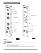
COMPONENT PANEL COMPONENTS PORCELAIN BLOCK ASSEMBLY PORCELAIN BLOCK ASSEMBLY TRANSFORMER TRANSFORMER MOTOR CONTROL RELAYS HEATING RELAY IGNITION MODULE BOARD IGNITION MODULE BOARD IGNITION MODULE IGNITION MODULE HEATING RELAY PORCELAIN BLOCK ASSEMBLY PORCELAIN BLOCK ASSEMBLY SG4D/SG6D PL-56047 SG4C/SG6C PL-56048 Procedure Disconnect the electrical power to the machine and follow lockout / tagout procedures. 1. Remove the right side panel as outlined under Covers and Panels. 2.
7. Remove the probe from the bracket(s). TEMPERATURE PROBE Disconnect the electrical power to the machine and follow lockout / tagout procedures. 1. Remove the right-side panel as outlined under Covers and Panels. 2. Disconnect probe leads from the solid state temperature controller on the SG4D/SG6D or the computer controller on the SG4C/SG6C. 3. Remove the racks and right rack support. 4. Remove the upper and lower door seals. SG4C/SG6C Temperature Probe Shown 8.
GAS BURNERS 5. Reverse the procedure to install and check for proper operation. Disconnect the electrical power to the machine and follow lockout / tagout procedures. A. Ensure the spacers are in place on the ignition wires. The spacers are intended to keep the ignition wires from laying flat on the oven chassis. Shut off the gas before servicing B. Ensure that the bracket on the back of the burner is inserted into the slot at the rear of the burner chamber. the oven. 1.
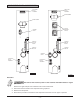
3. Disconnect compression fittings from the valve. GAS ORIFICE Disconnect the electrical power to the machine and follow lockout / tagout procedures. Shut off the gas before servicing the oven. 1. Remove the lower front cover as outlined under Covers and Panels. 2. Remove the bolts securing the gas manifold and place manifold aside. 4. Loosen the bolts securing the valve and bracket assembly, then remove the screws securing the valve to the bracket. 3. There are two gas orifices on the manifold.
IGNITION CONTROL MODULE SPARK IGNITER AND FLAME SENSE Disconnect the electrical power to the machine and follow lockout / tagout procedures. Disconnect the electrical power to the machine and follow lockout / tagout procedures. 1. Remove the right side cover as outlined under Covers and Panels. Shut off the gas before servicing the oven. 2. Loosen the screws securing the mounting bracket to the component panel and remove the bracket. 1. Remove the two gas burners as outlined under Gas Burners. 2.
5. Remove the screws that secure the motor mounting plate to the rear wall. BLOWER AND MOTOR Disconnect the electrical power to the machine and follow lockout / tagout procedures. 1. Remove racks. 2. Remove the screws securing the snorkel and remove the snorkel. 6. Place a piece of cardboard on the bottom of the oven cavity to protect its surface from any damage during motor assembly removal. 7. Pull the motor assembly into the oven cavity and place it on the cardboard. 8.
OVEN DOORS AND BEARINGS FRONT VIEW OF MOTOR FROM INSIDE OVEN CAVITY Disconnect the electrical power to the machine and follow lockout / tagout procedures. 1. Remove the top front cover and bottom front cover as outlined under Covers and Panels. 2. Remove the door switch lever. MOTOR ROTATES CLOCKWISE PL-56051 12. Slide blower onto motor shaft until hub is flush with end of shaft, then tighten setscrews. 13.
7. The top and bottom bearings are now accessible for inspection and/or replacement if needed. DOOR CATCH ROLLER ASSEMBLY (INDEPENDENT DOORS) NOTE: For units with serial number starting with 48 made before 8/13/07 and serial number starting with 54 made before 8/27/07. A. If bearings are OK, proceed to step 8. B. If replacing the top bearing, remove the top bearing retainer and top bearing. Disconnect the electrical power to the machine and follow lockout / tagout procedures. 1.
2. Remove the door handle, then remove the outer door panel. DOOR SWITCH 3. Lift out the inner door panel window assembly. Disconnect the electrical power to the machine and follow lockout / tagout procedures. 4. Remove the door seal from the inside of the left door only. 5. Remove the screws securing the window tabs to the door bracket and lift the window assembly out from the door frame. 1. Remove the top front cover as outlined under Covers and Panel. 2. Disconnect the lead wires to the door switch.
INTERIOR LIGHTS HIGH LIMIT THERMOSTAT Disconnect the electrical power to the machine and follow lockout / tagout procedures. Disconnect the electrical power to the machine and follow lockout / tagout procedures. 1. Remove the top four racks from the oven. 1. Remove the racks from the oven. 2. Remove the high limit thermostat cover/ mounting plate. It is located at the top of the oven cavity. 2. Unscrew the glass lens for the light being replaced, then unscrew the bulb.
5. Attach the lead wires to the replacement socket. Fan Installation Tips • The fan must be installed so air is pulled from the rear of the oven and blown into the control area. The arrow on the fan body indicates airflow direction and should be pointing toward the controls. NOTE: Ensure the case is connected to the green ground wire. 6. Insert the socket into the hole in the oven and push until the socket is held in place by the retaining tabs.
SERVICE PROCEDURES AND ADJUSTMENTS Certain procedures in this section require electrical test or measurements while power is applied to the machine. Exercise extreme caution at all times. If test points are not easily accessible, discern power, attach test equipment and reapply power to test. 8. Check for voltage to the switching output. SOLID STATE TEMPERATURE CONTROLLER TEST (SG4D/SG6D) a.
b. 7. Calculate the average oven temperature by adding the actual minimum temperature to the actual maximum temperature and dividing by 2. If incorrect, check temperature probe as outlined under Temperature Probe Test (SG4D/SG6D). 1) If temperature probe is functioning properly and the temperature controller failed the test in 8c above, replace the temperature control and check for calibration as outlined under Solid State Temperature Controller Calibration (SG4D/SG6D). EXAMPLE: Oven set to 350°F.
TEMPERATURE PROBE TEST (SG4D/SG6D) Disconnect the electrical power to the machine and follow lockout / tagout procedures. The temperature probe used in conjunction with the Solid State Temperature controller is an RTD (resistance temperature detector) of the Thermistor type. As temperature increases the resistance value decreases. Test Steps 1. Remove the right side panel as outlined under Cover and Panels in Removal and Replacement of Parts. 2.
3. Listed are the parameters and data in the setup mode. COMPUTER CONTROLLER (SG4C/SG6C) ALTERNATING ON DISPLAY Operation MENU Refer to the Installation & Operation Manual for specific operating instructions. Setup Mode Use the setup mode to verify that the control is configured to the factory settings which result in the proper operation of the oven. If the CAL1 parameter is other than zero, see Computer Control Calibration (SG4C/SG6C).
C. Press the set key again to save the change, then exit the temperature set mode. Solid State Relay Test 1. Remove the right side panels as outlined under Covers and Panels in Removal and Replacement of Parts. 4. Allow the oven temperature to stabilize (normally three cycles). 2. Turn the power switch to the ON position. 5. Compare the controls set point temperature to the thermocouple meter reading when the heat light goes out. 3.
4. Install hose barb adapter and attach manometer tube. GAS PRESSURE ADJUSTMENT Disconnect the electrical power to the machine and follow lockout / tagout procedures. Accurate gas pressure adjustments can only be made with the gas on and the burner lit. If the incoming line pressure to the valve is less than the minimum stated, then the manifold pressure cannot be set correctly. 1. Turn gas supply off at manual shutoff valve. 2.
The following steps require power to be applied to the unit during the test. Use extreme caution at all times. VERIFICATION OF SPARK AT IGNITOR Disconnect the electrical power to the machine and follow lockout / tagout procedures. 4. Plug the oven in and set the temperature controller to the maximum setting. 5. Turn the power switch ON. 6. Sparking should occur after a 4 second delay and continue for 7 seconds. The cycle will repeat twice after a 15 second purge time.
BLOWER ADJUSTMENT FLAME CURRENT MEASUREMENT Disconnect the electrical power to the machine and follow lockout / tagout procedures. MICROAMP METER 4 10 1. Remove the blower motor and mounting assembly as outlined under Blower and Motor in Removal and Replacement of Parts. S1 56 55 V1 8 V2 59 57 C-2 NC W S1 S2 S1 1 2 3 RED DIAGNOSTIC INDICATOR 345519-4 424471-G1 LED 56 U FENWAL DUAL CHANNEL IGNITION MODULE 52 T LEFT BURNER 24V FC2GND S2 FC1- 2 FC1+ 48 RIGHT BURNER S2 2.
DOOR ADJUSTMENT DOOR STRIKE ADJUSTMENT (INDEPENDENT DOORS) Disconnect the electrical power to the machine and follow lockout / tagout procedures. NOTE: For units with serial number starting with 48 made after 8/12/07 and serial number starting with 54 made after 8/26/07. 1. Check the doors to make sure they have an equal gap between them and that the vertical edge of the door is parallel to the vertical door seal. If the doors are not positioned in this manner, adjust the doors as described.
6. Place a standard flat screwdriver through the opening in the top channel into the slot in the cylinder of the catch assembly. DOOR CATCH ROLLER ADJUSTMENT NOTE: For units with serial number starting with 48 made before 8/13/07 and serial number starting with 54 made before 8/27/07. Disconnect the electrical power to the machine and follow lockout / tagout procedures. 1. Remove the top front cover as outlined under Cover and Panels in Removal and Replacement of Parts. 2.
ELECTRICAL OPERATION No Ignition Light (SG4C/SG6C) - Lit when power is turned ON, during ignition trial and gas purge time and when no flame is detected by flame sensor. If the oven fails to ignite after three attempts, it will remain lit until power is reset. COMPONENT DESCRIPTION Master Switch (S1) - Determines the mode of operation; ON, OFF or OVEN COOL Temperature Probe (SG4D/SG6D) - This temperature probe is a thermistor device.
Plug, Socket and Components (SG4D/SG6D) CONTROL PANEL (REAR VIEW) PORCELAIN BLOCK ASSEMBLY 1S ON/OFF/ COOLDOWN SWITCH COMPONENT PANEL (FRONT VIEW) 1 4 2 5 3 6 N H IN 1T TRANSFORMER OUT 1 1LT 2 ON 1 2LT 2 HEAT 1 3 LT 2 INDICATOR LIGHTS NO IGNITION 5 COM 6 3 NO 7 2 (COM AC) SOLID STATE THERMOSTAT 4 (120VAC) IGNITION CONTROL MODULE 9 (240VAC) POWER CONTROL 1 HEAT RELAY (R3) 4 12 13 N 14 H 1 COOK TIMER 2S LIGHT SWITCH 8 9 GROUND 3 4 5 1 4 2 5 1 4 2 5 3 6 3 6 3S FAN S
Plug, Socket and Components (SG4C/SG6C) CONTROL PANEL (REAR VIEW) COMPONENT PANEL (FRONT VIEW) PORCELAIN BLOCK ASSEMBLY 2J (FEMALE) N IN H 1T TRANSFORMER OUT 3J (FEMALE) 8 9 4 5 6 1 2 3 1 2 3 4 5 6 7 8 9 PIN NUMBERS EVENT 2 OUT EVENT 1 OUT EVENT COM (IN) EVENT 1 (IN) EVENT 4 OUT EVENT 3 OUT NOT USED POWER 5V EVENT 2 (IN) 1 2 3 4 5 6 3J 12 9 6 3 11 8 5 2 10 7 4 1 NOT USED SSRI SSRI NOT USED NOT USED L1 24V- SOLID STATE RELAY (SSR1) LOAD 2J 7 OPER. TEMP. 0-30 DEG.
2. Set temperature controller dial to desired temperature. SEQUENCE OF OPERATIONS SG4D/SG6D Controller A. Contacts J3 and J5 close. with Solid State Temperature 3. Power switch (S1) is turned ON. Schematic 424373-1 will be used to explain the electrical sequence of operation. NOTE: Power is available to the oven light switch A. Component cooling fan energized. Cook Cycle B. ON light (amber) is lit. 1. Conditions C. Power to timer terminal C. A. Oven connected to correct voltage. D.
4. Heating circuit is powered. Timer Cycle A. No ignition light (red) comes ON. The timer operates independently of the heating cycle. Additional time can be set or the timer can be turned OFF throughout the cooking cycle. B. Module performs a self diagnostic test for 4 seconds. 1. With the master switch turned ON, power is supplied to timer. C. Second valve (main) on the gas valve is energized. Gas starts to flow to burners. A. Set the timer to desired time. D.
2. Power switch (S1) turned to COOL DOWN. SG4C/SG6C with Computer Controller A. Power to fan speed switch (S3). Set fan speed switch to either HI or LO. Schematic 426575-1 will be used to explain the electrical sequence of operation. 3. If door is closed, power is supplied to one side of the following components: Normal Cook Cycle 1. Conditions A. Power ON light (Amber) comes ON. A. Oven connected to correct voltage. B. Transformer (T1) energized.
C. Power to terminal 1 on solid state relay 1 SSR1-load side and solid state relay 2 SSR2-load side. B. Heat relay coil (R1) energized. 1) (R1) contacts (N.O.) close and the heating circuit is powered. D. Component cooling fan energized. 2) Oven heat light on the control comes on. E. Transformer (T1) is energized, 24 volt output. C. Ignition module is energized. 1) Power (24 VAC) to one side of the following components: heat relay (R1) normally open (N.O.
2) Oven heat LED on the control goes out. 3) Oven ready LED on the control comes ON. 4) Electronic beeper sounds momentarily. B. The computer control 5 VDC output from pins C2-1 (-) and C2-8 (+) is activated and SSR2 relay is energized. 1) Power (120 VAC) is applied to the convection fan motor low speed terminal. C. The oven will continue to cycle on the computer control until the doors are opened or power switch (S1) is turned to the OFF or COOL DOWN position.
WIRING DIAGRAMS – 38 –
– 39 – 426574 Rev. C 734 COMPUTER CONTROL DUAL BURNER CONVECTION OVENS 120 & 200 V.
SCHEMATICS BLACK WHITE 120 VOLT L1 L2 200-240V C1-6 6 C1-2 C1-1 POWER ON POWER SWITCH ON/OFF/COOL SHOWN ON 2 GND. 1 40 1 2 41 HEATING S1 36 POWER LEVEL 39 3 43 39 42 THERMOSTAT 28 5 40W PROBE 35 35 20 OVEN LAMP SWITCH 4 C1-4 10 40W 10 92 OPEN C3-1 3 C3-2 90 OVEN LAMP C1-10 44 90 OVEN LAMP DOOR SWITCH 8 C1-9 C1-3 91 9 S2 36 1 HOUR TIMER BUZZER HOLD NC C 64 66 NO 65 M WHT.
GAS CONVECTION OVEN SG4 WITH WATLOW 734 CONTROL 426575-1 – 41 – REV.
TROUBLESHOOTING POSSIBLE CAUSES SYMPTOMS Blower motor doesn't run in OVEN COOL or ON position. Line voltage. Power/Master switch malfunction. Fan switch malfunction. Interconnection wiring malfunction. Blower motor doesn't run in the ON position. Cool Down functions OK. Door switch malfunction. Power/Master switch contacts inoperative. Interconnecting wiring malfunction. Blower motor doesn't run in OVEN COOL position. Runs OK in ON position. Power/Master switch malfunction.
TROUBLESHOOTING SYMPTOMS POSSIBLE CAUSES Mechanical timer inoperative or not functioning properly. Interconnecting wiring malfunction. Line voltage incorrect. Timer malfunction. Component cooling fan does not run. Motor inoperable. Interconnecting wiring malfunction. Uneven cooking. Convection fan motor speed/direction. Poor combustion. Gas pressure incorrect. Exhaust vent plugged or obstructed. Snorkel vent plugged or obstructed. Air flow baffles missing or damaged. Intermittent problems.
ERROR CODES CODE AND PROBLEM PROBABLE CAUSE SOLUTION Er01 - ROM check sum error Internal ROM malfunction Cycle power. Er02 - RAM check sum error Internal RAM malfunction Cycle power. Er03 - Ambient sensor error Ambient temperature is below 32°F Check ambient temperature at the control. Er04 - Configuration error Microprocessor malfunction Cycle Power. Ero5 - EEprom error Power loss while storing data Cycle Power.