SERVICE MANUAL ELECTRIC COMBI OVENS MODEL ML VCE6H 126177 VCE10H 126178 VCE10F 126179 VCE20H 126172 VCE20F 126173 VCE10F SHOWN ON STAND - NOTICE This Manual is prepared for the use of trained Vulcan Service Technicians and should not be used by those not properly qualified. If you have attended a Vulcan Service School for this product, you may be qualified to perform all the procedures described in this manual. This manual is not intended to be all encompassing.
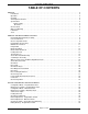
ELECTRIC COMBI OVENS TABLE OF CONTENTS GENERAL . . . . . . . . . . . . . . . . . . . . . . . . . . . . . . . . . . . . . . . . . . . . . . . . . . . . . . . . . . . . . . . . . . . . . . . . . . . . . Introduction . . . . . . . . . . . . . . . . . . . . . . . . . . . . . . . . . . . . . . . . . . . . . . . . . . . . . . . . . . . . . . . . . . . . . . . . Operation . . . . . . . . . . . . . . . . . . . . . . . . . . . . . . . . . . . . . . . . . . . . . . . . . . . . . . . . . . . . . . . . . . . . . . . .
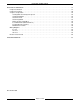
ELECTRIC COMBI OVENS ELECTRICAL OPERATION . . . . . . . . . . . . . . . . . . . . . . . . . . . . . . . . . . . . . . . . . . . . . . . . . . . . . . . . . . . . . . Component Function . . . . . . . . . . . . . . . . . . . . . . . . . . . . . . . . . . . . . . . . . . . . . . . . . . . . . . . . . . . . . . . . Component Location . . . . . . . . . . . . . . . . . . . . . . . . . . . . . . . . . . . . . . . . . . . . . . . . . . . . . . . . . . . . . . . . Sequence of Operation . . . . . . . . . . . . . . .
ELECTRIC COMBI OVENS - GENERAL GENERAL INTRODUCTION STACKING KIT INSTRUCTIONS General The procedures in this manual apply to all models unless otherwise specified. All of the information, illustrations and specifications contained in this manual are based on the latest product information available at the time of printing. When servicing stacked ovens and disassembly is required, refer to the Stacking Kit Instructions for specific assembly procedures.
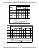
ELECTRIC COMBI OVENS - GENERAL Electrical MACHINE AMPERAGE (3 PHASE/ 60HZ) 1 MODEL POWER (KW) RECOMMENDED CIRCUIT PROTECTION 3 PER LINE 2 208V 240V 480V 208V 240V 480V VCE6H 9 25 22 11 35 30 15 VCE10H 18 50 43 22 70 60 30 VCE10F 18 50 43 22 70 60 30 VCE20H 24 67 58 29 90 80 40 VCE20F 36 100 87 43 125 110 60 NOTES: 1. Amperage values in the table are nominal. Tolerance is +5/-10%. 2. Line currents must be measured in full power convection heat mode. 3.
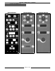
ELECTRIC COMBI OVENS - GENERAL OVEN CONTROLS PROGRAMMABLE DELUXE MANUAL Page 6 of 68 STANDARD MANUAL
ELECTRIC COMBI OVENS - GENERAL WATER CONDITIONING LUBRICATION Furnishing the steam generator with treated water to reduce scale formation is important. Scale formation will reduce steam output, cause premature component failure, and shorten equipment life. Most water supplies contain scale producing minerals such as Calcium and Magnesium. As steam is generated, the minerals remain and dissolve into the water.
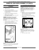
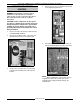
ELECTRIC COMBI OVEN - REMOVAL AND REPLACEMENT OF PARTS REMOVAL AND REPLACEMENT OF PARTS RACK GUIDE/FILTER/EXHAUST ASSEMBLY 1. Turn the oven off. 2. Remove the racks (if equipped). 3. Push the rack guide to rear of oven to remove the rack guide tabs from slots in the exhaust assembly (10 level). 4. Lift the rear of the rack guide up and pull the guide out of the oven cavity. 5. Lift the filter up, then pull forward to remove the filter (2 filters on 20 level).
ELECTRIC COMBI OVEN - REMOVAL AND REPLACEMENT OF PARTS Rear Panel 1. 2. OVEN TEMPERATURE PROBE Remove the screws from the rear oven panel. Hold the panel in place before removing the last panel screw. Access the inside edge of the panel at the bottom left and disconnect the ground wire (if present). 3. Lower the panel to remove from oven. 4. Reverse procedure to install. WARNING: DISCONNECT THE ELECTRICAL POWER TO THE MACHINE AT THE MAIN CIRCUIT BOX.
ELECTRIC COMBI OVEN - REMOVAL AND REPLACEMENT OF PARTS PROGRAMABLE OVEN CONTROL 4. Remove the hex nuts securing the CPU board to the display/keypad board. 5. Pull outwards on the CPU board and lift it off from the display/keypad board pin connections. WARNING: DISCONNECT THE ELECTRICAL POWER TO THE MACHINE AT THE MAIN CIRCUIT BOX. PLACE A TAG ON THE CIRCUIT BOX INDICATING THE CIRCUIT IS BEING SERVICED.
ELECTRIC COMBI OVEN - REMOVAL AND REPLACEMENT OF PARTS 6. Remove the display/keypad board from the control panel by removing the mounting nuts. 7. Reverse procedure to install. 4. Remove the oven control board from the control panel by removing the mounting nuts. 5. Reverse procedure to install. MANUAL OVEN CONTROLS RELAY BOARD WARNING: DISCONNECT THE ELECTRICAL POWER TO THE MACHINE AT THE MAIN CIRCUIT BOX. PLACE A TAG ON THE CIRCUIT BOX INDICATING THE CIRCUIT IS BEING SERVICED.
ELECTRIC COMBI OVEN - REMOVAL AND REPLACEMENT OF PARTS 3. 4. Release the clips on the back of the mounting rail. NOTE: If only the blower is being removed, reverse the procedure at this point to install. 5. Remove the rear panel as outlined under “COVERS AND PANELS”. 6. Disconnect the lead wires from the motor. 7. Remove the motor from the back of the oven by removing the mounting nuts. 8. Remove the cover plate and seal from inside the oven cavity. Reverse procedure to install.
ELECTRIC COMBI OVEN - REMOVAL AND REPLACEMENT OF PARTS Installation 1. Mount the motor to the back of the oven. Tighten the bolts enough to hold the motor in place, but allow some movement. 2. Ensure that the motor shaft is centered (use shaft centering tool) in the motor shaft hole and tighten mounting bolts. NOTE: Remove all traces of motor seal grease from the motor shaft. 7. Install the seal cover plate and then the blower. HEATING ELEMENTS 3. Remove the shaft centering tool. 4.
ELECTRIC COMBI OVEN - REMOVAL AND REPLACEMENT OF PARTS Steam Generator 1. Turn off the water supply to the steam generator. 2. Remove the right side panel as outlined under “COVERS AND PANELS”. 3. Remove the thermal fuse and protective sleeve from the heater thermowell. 4. Disconnect the heating element lead wire connections. 5. Remove the heating element from the steam generator by removing the mounting nuts.
ELECTRIC COMBI OVEN - REMOVAL AND REPLACEMENT OF PARTS STEAM GENERATOR DRAIN PUMP 1. VENT DAMPER ASSEMBLY Turn off the oven and allow the steam generator to drain. WARNING: DISCONNECT THE ELECTRICAL POWER TO THE MACHINE AT THE MAIN CIRCUIT BOX. PLACE A TAG ON THE CIRCUIT BOX INDICATING THE CIRCUIT IS BEING SERVICED. 2. Turn off the water supply. 3. Remove the right side panel as outlined under “COVERS AND PANELS”. 4. Disconnect lead wires and hoses connected to the drain pump. 5.
ELECTRIC COMBI OVEN - REMOVAL AND REPLACEMENT OF PARTS Sealing Washer 1. 2. Remove the right side panel as outlined under “COVERS AND PANELS”. 4. Rotate the extension rod approximately 90 degrees by hand. 5. Examine the vent from inside the cavity. Open the oven door and remove the rack guide, filter and exhaust assembly as outlined under “RACK GUIDE/FILTER/EXHAUST ASSEMBLY”. A. If the mounting nut is visible, proceed to step 6. B.
ELECTRIC COMBI OVEN - REMOVAL AND REPLACEMENT OF PARTS 5. Remove the water equalization tube. 4. Disconnect water and steam equalization tube from the steam generator. If necessary, loosen or remove drain pump mounting nuts to remove tube. 10 LEVEL SHOWN 6. Reverse procedure to install. A. NOTE: Unless replacing the heating element(s), it not necessary to remove the heating element lead wires. STEAM GENERATOR TANK 1. B. Turn the oven off and allow the steam generator tank to drain.
ELECTRIC COMBI OVEN - REMOVAL AND REPLACEMENT OF PARTS 4. OVEN DOOR Open the inner door glass and remove the cring clamps from the rear snap catches, unsnap at the rear then lift off. WARNING: DISCONNECT THE ELECTRICAL POWER TO THE MACHINE AT THE MAIN CIRCUIT BOX. PLACE A TAG ON THE CIRCUIT BOX INDICATING THE CIRCUIT IS BEING SERVICED. Removal 1. Remove the left and right side panels as outlined under “COVERS AND PANELS”. 2.
ELECTRIC COMBI OVEN - REMOVAL AND REPLACEMENT OF PARTS DOOR LAMP OVEN DOOR HINGES WARNING: DISCONNECT THE ELECTRICAL POWER TO THE MACHINE AT THE MAIN CIRCUIT BOX. PLACE A TAG ON THE CIRCUIT BOX INDICATING THE CIRCUIT IS BEING SERVICED. 1. Remove the screws holding the cover and gasket. WARNING: DISCONNECT THE ELECTRICAL POWER TO THE MACHINE AT THE MAIN CIRCUIT BOX. PLACE A TAG ON THE CIRCUIT BOX INDICATING THE CIRCUIT IS BEING SERVICED. 1. Remove and disassemble the door as outlined under “OVEN DOOR”.
ELECTRIC COMBI OVEN - REMOVAL AND REPLACEMENT OF PARTS DOOR MAGNETIC REED SWITCH 5. Apply red silicone to the replacement seal and install the seal to the glass edge. The vent holes must be installed to the outside to allow the seal to contract when the door is closed. 6. Adjust door closure, if necessary, as outlined under “OVEN DOOR AND DOOR LOCK ADJUSTMENT” in “SERVICE PROCEDURES AND ADJUSTMENTS”. WARNING: DISCONNECT THE ELECTRICAL POWER TO THE MACHINE AT THE MAIN CIRCUIT BOX.
ELECTRIC COMBI OVEN - REMOVAL AND REPLACEMENT OF PARTS 4. Remove the spring and positioning plate from the locking arm. 5. Reverse procedure to install and adjust as outlined under “OVEN DOOR ADJUSTMENT” in “SERVICE PROCEDURES AND ADJUSTMENTS”. Disassembly 1. Remove the three screws that secure the motor and switch assembly. 2. Remove the motor, gear box and switch assembly from the locking mechanism. Remove the two bolts from the locking mechanism. The springs, locking arm and bushings can be removed.
ELECTRIC COMBI OVEN - REMOVAL AND REPLACEMENT OF PARTS POWER SUPPLY BOARD AND TRANSFORMER CONTACTORS WARNING: DISCONNECT THE ELECTRICAL POWER TO THE MACHINE AT THE MAIN CIRCUIT BOX. PLACE A TAG ON THE CIRCUIT BOX INDICATING THE CIRCUIT IS BEING SERVICED. 1. 2. Remove the right side panel as outlined under “COVERS AND PANELS”. WARNING: DISCONNECT THE ELECTRICAL POWER TO THE MACHINE AT THE MAIN CIRCUIT BOX. PLACE A TAG ON THE CIRCUIT BOX INDICATING THE CIRCUIT IS BEING SERVICED. 1.
ELECTRIC COMBI OVEN - REMOVAL AND REPLACEMENT OF PARTS OVEN CAVITY DRAIN 6. Remove the drain vent pipe from the drain. 7. Disconnect the drain cool down water hose from the drain nipple extension. 8. Unscrew the drain line piping from the bottom of the oven then remove the oven drain. 9. Reverse procedure to install. WARNING: DISCONNECT THE ELECTRICAL POWER TO THE MACHINE AT THE MAIN CIRCUIT BOX. PLACE A TAG ON THE CIRCUIT BOX INDICATING THE CIRCUIT IS BEING SERVICED. 1.
ELECTRIC COMBI OVENS - SERVICE PROCEDURES AND ADJUSTMENTS SERVICE PROCEDURES AND ADJUSTMENTS WARNING: CERTAIN PROCEDURES IN THIS SECTION REQUIRE ELECTRICAL TEST OR MEASUREMENTS WHILE POWER IS APPLIED TO THE MACHINE. EXERCISE EXTREME CAUTION AT ALL TIMES. IF TEST POINTS ARE NOT EASILY ACCESSIBLE, DISCONNECT POWER, ATTACH TEST EQUIPMENT AND REAPPLY POWER TO TEST. CONFIGURATION MODE PROGRAMABLE CONTROL WARNING: DISCONNECT THE ELECTRICAL POWER TO THE MACHINE AT THE MAIN CIRCUIT BOX.
ELECTRIC COMBI OVENS - SERVICE PROCEDURES AND ADJUSTMENTS NOTE: The temperature selected in the table below will also be the highest starting point temperature available, when the steam mode is selected.
ELECTRIC COMBI OVENS - SERVICE PROCEDURES AND ADJUSTMENTS 3. 4. The DISPLAY and LED test consists of flashing all displays and LED’s. The word “test” will flash intermittently as the temperature display is tested. Verify all the DISPLAYS and LED’s are flashing. This test will continue until a key is pressed to advance to the next step. The RELAY test consist of selecting a particular relay by its code number (01 to 11) with the TEMP UP and TEMP DOWN keys.
ELECTRIC COMBI OVENS - SERVICE PROCEDURES AND ADJUSTMENTS 3. 4. 5. 6. 7. dSCL is displayed in the time display and the number of clean cycles completed (deliming of steam generator) is displayed in the temperature display. The number cannot be changed or modified. Press the TIME key to advance to the next step.
ELECTRIC COMBI OVENS - SERVICE PROCEDURES AND ADJUSTMENTS CONVECTION FAN MOTOR TYPE POSITION 1 (MINIMUM) POSITION 2 (MAXIMUM) 1 motor Leroy-Somer (Hanning) 8 55 1 motor Brook-Crompton * 8 60 2 motors Leroy-Somer (Hanning) 46 120 2 motors Brook-Crompton 30 90 1 motor Leroy-Somer (Hanning) and 1 motor Brook-Crompton 38 105 NOTE: SWITCH/ KEYPAD/KNOB (*) Ovens are shipped from the factory with this motor and the oven control is configured accordingly.
ELECTRIC COMBI OVENS - SERVICE PROCEDURES AND ADJUSTMENTS CODE RELAY COMPONENT TEST 01 K1 door motor Door magnetic reed switch. Result will be displayed automatically. Rotate the door handle to change the condition. Press and hold the TEMP key to close the door; release to open. 02 K2 cavity vent motor Cavity vent micro switch. Result will be displayed automatically. Press and hold the TEMP key to change condition.
ELECTRIC COMBI OVENS - SERVICE PROCEDURES AND ADJUSTMENTS HEATING ELEMENTS OVEN DOOR ADJUSTMENT WARNING: THE FOLLOWING STEPS REQUIRE POWER TO BE APPLIED TO THE UNIT DURING THE TEST. USE EXTREME CAUTION AT ALL TIMES. 1. Measure the voltage at the heating element terminals and verify it against the data plate voltage. A. 2. 3. 1. Turn the oven off. 2. Check the level of the oven from left to right and front to back, in the exact location where the oven is to be positioned.
ELECTRIC COMBI OVENS - SERVICE PROCEDURES AND ADJUSTMENTS 8. Position the door roller against the “striking” edge of the locking arm but do not close the door. 10. With the door in the closed position the roller should be cradled in the locking arm hook. 11. Replace the control panel. A. Observe the position of the door roller to the locking arm. B. Adjust the door roller so it mates at the “striking edge” (bottom of the sloped edge) of the locking arm.
ELECTRIC COMBI OVENS - SERVICE PROCEDURES AND ADJUSTMENTS A. If the space is larger at the hinge end, remove shim(s) from behind the hinges or from in front of the door locking mechanism. B. If the space is smaller at the hinge end, add shim(s) behind the hinges or in front of the door locking mechanism. 4. To adjust the buzzer volume, turn the buzzer volume adjustment screw until the desired volume is obtained. 5.
ELECTRIC COMBI OVENS - SERVICE PROCEDURES AND ADJUSTMENTS 4. To adjust the buzzer volume, turn the buzzer volume adjustment screw until the desired volume is obtained. 1. Programmable oven control - Press the ON key to turn the oven on and press the PROG key to enter the programed cooking mode. Program number “00" is displayed in the program display. Press the down key once, to select the clean cycle program or if at program 98 press the up key once to select the clean cycle program.
ELECTRIC COMBI OVENS - SERVICE PROCEDURES AND ADJUSTMENTS B. If there is no water treatment system installed in the water line to the steam generator, then add an amount of vinegar equal to the tank volume for the combi model. See table below. 1) Add the vinegar to the steam generator through the opening in the oven cavity. Use the funnel and flexible tube provided with the oven. TANK VOLUME (GAL) (QT) AMOUNT OF SCALEKLEEN ADDED TO FEEDER BOWL (7 OZ. PACKET SIZE) 1, 2 VCE6H 0.8 3.2 1.0 Packet or 7.
ELECTRIC COMBI OVENS - SERVICE PROCEDURES AND ADJUSTMENTS 1) BATTERY BACKUP PROGRAMABLE CONTROL The battery backup module allows the SRAM (static ram) to retain the configuration and program information in memory if there is a power loss. The battery backup may come in a two piece configuration of an SRAM chip mounted onto a battery module or a one piece SRAM and battery module combination. The 28 pin non-volatile SRAM/Battery module is located on the CPU board.
ELECTRIC COMBI OVENS - SERVICE PROCEDURES AND ADJUSTMENTS Battery Replacement WARNING: DISCONNECT THE ELECTRICAL POWER TO THE MACHINE AT THE MAIN CIRCUIT BOX. PLACE A TAG ON THE CIRCUIT BOX INDICATING THE CIRCUIT IS BEING SERVICED. Install the SRAM and battery module assembly onto the CPU board with the notches pointing up. Carefully line up the battery module pins and insert them into the socket on the CPU board. Ensure that all pins are inserted properly.
ELECTRIC COMBI OVEN - ELECTRICAL OPERATION ELECTRICAL OPERATION COMPONENT FUNCTION 1A Relay Board . . . . . . . . . . . . . . . Takes the inputs from oven control board to operate relays that control power to the components. 2A Oven Control . . . . . . . . . . . . . . Manages all functions of oven operation, takes input signals and performs outputs as required. Referred to as the CPU board on the Programable control and the Display/Keypad/CPU board on the manual controls. 3A Display/Keypad Board .....
ELECTRIC COMBI OVEN - ELECTRICAL OPERATION 2SOL Drain Cool Down Solenoid Valve . . . . . . . . . . 3SOL Water Fill Solenoid Valve . . . . . . . . . . . . . . . Admits cold water to the cavity drain and mixes with the hot to condense steam and cool the drain water before entering the floor drain. This solenoid valve is energized whenever the steam generator heating elements are energized. Does not operate during a drain cycle.
ELECTRIC COMBI OVEN - ELECTRICAL OPERATION KM5 (5CON) ................. Contactor for steam generator heating elements; (7HTR) on 20 level half and (8HTR) on 20 level full only. KM6 (6CON) ................. Contactor for convection heating elements; (1HTR) on 6 level; (1HTR) inner on 10 level; (1HTR) Inner top and (5HTR) inner bottom on 20 level. KM7 (7CON) ................. Contactor for convection heating elements; (3HTR) outer on 10 level; (3HTR) outer top and (6HTR) outer bottom on 20 level.
ELECTRIC COMBI OVEN - ELECTRICAL OPERATION COMPONENT LOCATION Page 40 of 68
ELECTRIC COMBI OVEN - ELECTRICAL OPERATION Page 41 of 68
ELECTRIC COMBI OVEN - ELECTRICAL OPERATION SEQUENCE OF OPERATION The convection and steam heating theory outlined below, covers the programable and manual oven controls unless otherwise stated. Heating Mode and Cavity Fan Speeds KM1 = 1/2 power and full speed cavity fan(s). KM2 = 1/2 power and half speed cavity fan(s). KM1 + KM2 = Full power and full speed cavity fan(s). KM3 and KM5 = Steam mode regulation (KM5 on 20 level only). KM6 and KM7 = Convection mode regulation.
ELECTRIC COMBI OVEN - ELECTRICAL OPERATION On 20 level machines (half and full size) the heating mode regulation is the same but with these additional points to remember: Top and bottom heating elements operate independently and correspond to the top and bottom cavity temperature probes. Display always shows the lowest temperature.
ELECTRIC COMBI OVEN - ELECTRICAL OPERATION 2) Water Injection (Humidifier) Water can be injection onto the convection heating elements in the oven cavity and is used in these three ways: 1. 2. 3. Automatic Cooling (Programable & Manual Controls) - If the steam mode is selected after cooking in convection or combi mode and the cavity temperature is above 302°F, water is injected intermittently to cool the oven cavity.
ELECTRIC COMBI OVEN - ELECTRICAL OPERATION Programable Oven Control C. Oven cavity lamp energized. This sequence of operation is written for the combi oven models that use the programable oven control. The three heating modes outlined below (convection, steam and combi) are for manual operation of the oven. The automatic cooking methods (timed, temperature probe and delta t) are then outlined. D. Cooling fan(s) energized. E. Cavity vent motor energized.
ELECTRIC COMBI OVEN - ELECTRICAL OPERATION 3. Press the temp key to set the operating temperature (default setting is 302°F; adjustable range is 35 to 518°F). A. 4. 3. A. Start/Stop LED on. B. Convection heating elements energized and cycle as described under “HEATING REGULATION”. C. Steam generator pre-heats (initial start up only) as described under “STEAM PREHEAT”. NOTE: When degree symbol shows in the temperature display, convection and/or steam generator heating elements are energized. 1) 6.
ELECTRIC COMBI OVEN - ELECTRICAL OPERATION A. Start/Stop LED off. 1) B. Steam generator heating elements deenergized. C. Cavity fan motor(s) de-energized. NOTE: Whenever steam generator heating elements are on, the drain cool down solenoid is energized. D. Steam mode remains selected with LED on. D. Drain cool down solenoid energized. Cavity fan motor(s) energized. 5.
ELECTRIC COMBI OVEN - ELECTRICAL OPERATION 4. Cooking time expires. A. B. C. 5. A. Buzzer sounds for approximately 10 seconds on and 45 seconds off. The buzzer continues to cycle at these times until the Start/Stop key is pressed. Buzzer sounds for approximately 10 seconds on and 45 seconds off. The buzzer continues to cycle at these times until the Start/Stop key is pressed. B. Convection and/or steam generator heating elements de-energized. Probe temperature flashes in the time display. C.
ELECTRIC COMBI OVEN - ELECTRICAL OPERATION A. 3. NOTE: There is a four second time delay after pressing the off key to cancel the shut down sequence and resume normal operation. Press probe key. A. 4. Press the temp up or down keys to set the Delta T differential. Press the time up or down keys to set the final product temperature. Press Start/Stop key to begin the cooking cycle. NOTE: The Delta T differential can not be adjusted without stopping and starting the cycle again.
ELECTRIC COMBI OVEN - ELECTRICAL OPERATION 2. H. Cavity vent open. I. 240VAC supplied to relay board. J. Steam generator empty. K. Water supply on. 1. Conditions exist as described in “POWERING CONTROL”. 2. With the selector knob rotated to HEAT, the cooking cycle begins. Oven control runs a self diagnostic test. 1) 2) Proceed to the appropriate heating mode (convection, combi or steam) for the continuation of the sequence.
ELECTRIC COMBI OVEN - ELECTRICAL OPERATION 1) Steam Mode 1. Conditions exist as described in “POWERING CONTROL”. 2. With the selector knob rotated to STEAM, the cooking cycle begins.. A. Time LED is on and “- -:- - “ is displayed in the time display. B. Cavity set point temperature (default) is displayed in the temperature display. If the oven has not been turned off, the previous set point temperature is displayed. C. 1) 2) D.
ELECTRIC COMBI OVEN - ELECTRICAL OPERATION 1) Drain cool down solenoid energized. NOTE: Whenever steam generator heating elements are on, the drain cool down solenoid is energized. G. 3. 3. Cavity fan motor(s) energized. Press the temp key to set the operating temperature (the last temperature that was set is displayed; adjustable range is 35 to 518°F). The temperature symbol (°F or °C) will flash in the temperature display to indicate the cavity set point temperature can be adjusted. A.
ELECTRIC COMBI OVEN - ELECTRICAL OPERATION NOTE: To display the actual probe temperature for 5 seconds, press and hold the probe key. 3. 1. The control can be in any heating mode and the door in the open or closed position. 2. Rotate the selector knob to off. Press Start key to begin the cooking cycle. A. Start LED on. NOTE: The probe temperature can be adjusted throughout the cooking cycle by pressing the probe key and rotating the adjustment.
ELECTRIC COMBI OVEN - ELECTRICAL OPERATION WIRING DIAGRAMS 6 Level Page 54 of 68
ELECTRIC COMBI OVEN - ELECTRICAL OPERATION Page 55 of 68
ELECTRIC COMBI OVEN - ELECTRICAL OPERATION 10 Level Page 56 of 68
ELECTRIC COMBI OVEN - ELECTRICAL OPERATION Page 57 of 68
ELECTRIC COMBI OVEN - ELECTRICAL OPERATION 20 Level Page 58 of 68
ELECTRIC COMBI OVEN - ELECTRICAL OPERATION Page 59 of 68
ELECTRIC COMBI OVEN - ELECTRICAL OPERATION ELECTRIC HEATER CIRCUITS Page 60 of 68
ELECTRIC COMBI OVEN - ELECTRICAL OPERATION Page 61 of 68
ELECTRIC COMBI OVEN - ELECTRICAL OPERATION Page 62 of 68
ELECTRIC COMBI OVENS - TROUBLESHOOTING TROUBLESHOOTING WARNING: CERTAIN PROCEDURES IN THIS SECTION REQUIRE ELECTRICAL TEST OR MEASUREMENTS WHILE POWER IS APPLIED TO THE MACHINE. EXERCISE EXTREME CAUTION AT ALL TIMES. IF TEST POINTS ARE NOT EASILY ACCESSIBLE, DISCONNECT POWER, ATTACH TEST EQUIPMENT AND REAPPLY POWER TO TEST.
ELECTRIC COMBI OVENS - TROUBLESHOOTING SYMPTOM POSSIBLE CAUSES Convection heat error light and steam heat error light on. 1. 2. 3. Cavity high temperature limit(s) open (manual reset). Fuse F7 open. Steam generator thermal fuse(s) open. Cavity fan motor inoperative and cavity fan error light on. 1. Cavity fan motor values in the oven control configuration setup are incorrect. See “CONFIGURATION MODE PROGRAMABLE CONTROL” or “CONFIGURATION MODE MANUAL CONTROLS” in “SERVICE PROCEDURES”AND ADJUSTMENTS”.
ELECTRIC COMBI OVENS - TROUBLESHOOTING SYMPTOM No steam generation but cavity fan operates. POSSIBLE CAUSES 1. 2. 3. 4. 5. 6. 7. Oven displays “888F” or “888C” in the temperature display. 1. 2. 3. Oven displays “999F" or “999C" in the temperature display. 1. 2. 3. Cavity temperature is above steam temperature set point and oven is performing automatic cooling before steam generation can start. Water supply off. Steam generator thermal fuse(s) open. Steam generator heating element(s) malfunction.
ELECTRIC COMBI OVENS - TROUBLESHOOTING SYMPTOM Temperature display for cavity or cooking probe does not change after starting a cook cycle. POSSIBLE CAUSES 1. 2. 3. 4. Cooking probe temperature displays “32” in the time display. After approximately 10 minutes, “00"or “32” flashes and the buzzer sounds intermittently. Oven will not operate in probe mode. 1. 2. 3. Temperature display flashes current cavity temperature but oven will not heat or produce steam. 1.
ELECTRIC COMBI OVENS - TROUBLESHOOTING SYMPTOM Heating mode selector switch, adjustment knob or keypad button(s) inoperative (manual control). POSSIBLE CAUSES 1. 2. Door will not lock. 1. 2. 3. 4. 5. 6. Display/Keypad/CPU board malfunction. Verify keypad is functioning properly. See “DIAGNOSTIC TEST MODE MANUAL CONTROLS” under “SERVICE PROCEDURES AND ADJUSTMENTS”. If keypad test is inaccessible, the oven control board may not be properly mounted to the front panel.
ELECTRIC COMBI OVENS - TROUBLESHOOTING SYMPTOM POSSIBLE CAUSES Inner door glass breaks. 1. Glass installed incorrectly with conductive side toward oven cavity. See “OVEN DOOR” under “REMOVAL AND REPLACEMENT OF PARTS”. Steam generator drains continually. 1. 2. Relay board malfunction (K3, K5). Oven control board malfunction. Cavity fan motor squeaks. 1. 2. Motor seal - grease is dry or dirty. Motor shaft rubbing against the opening in the rear of the cavity.