INSTALLATION & OPERATION MANUAL ELECTRIC HEAVY DUTY RANGES MODELS VR, VS, VM, VEX, VMX AND VRC VR4 Range For additional information on Vulcan-Hart or to locate an authorized parts and service provider in your area, visit our website at www.vulcanhart.com VULCAN-HART DIVISION OF ITW FOOD EQUIPMENT GROUP, LLC F33210 (Rev. A 1-04) P.O. BOX 696, LOUISVILLE, KY 40201-0696 TEL. (502) 778-2791 www.vulcanhart.
The following models have been discontinued and are no longer available: VR1(C) VR3(C) VR6(C) VR7(C) 2 VS1 VS3 VS6 VS7 VM1 through VM7 VMX1 VMX2 VMX3 VEX1
INSTALLATION AND OPERATION MANUAL FOR ELECTRIC RANGES MODELS VR, VS, VM, VEX, VMX AND VRC INDEX SAVE THESE INSTRUCTIONS FOR FUTURE REFERENCE Vulcan ranges are produced with quality workmanship and material. Proper installation, usage and maintenance of your range will result in many years of satisfactory performance.
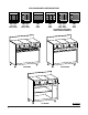
VULCAN RANGE CONFIGURATIONS VR1, VR2 VM1, VM2 VS1, VS2 VR1C, VR2C VR3, VR6 VM3, VM6 VS3, VS6 VR3C, VR6C VR5 VM5 VS5 VR5C VR4 VM4 VS4 VR4C VRC SERIES VR SERIES VS SERIES 4 VR3, VR6 VR7 VM3, VM6 VM7 VS3, VS6 VS7 VR3C, VR6C VR7C (SHOWN WITH OPTIONAL HIGH SPEED ELEMENTS) PL - 51130-1
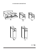
VULCAN RANGE CONFIGURATIONS VM1 VM2 VMX1 VMX2 VEX1 VEX2 VMX3 VEX3 PL - 51130-2 5
GENERAL The various Vulcan electric VR, VS, VM, VEX and VMX Family Series standard ranges and VRC Series convection ranges are equipped as follows: MODEL DESCRIPTION RANGES WITH STANDARD OVEN VR1 VR2 VR3 VR4 VR5 VR6 VR7 (3) 12" x 24" (305 x 610) hot tops. (3) 12" x 24" (305 x 610) all purpose plates, (2) with grease troughs on right and left sides and (1) without grease trough in the center. (2) 91/2" (241) dia. round French hot plates at left and (2) 12" x 24" (305 x 610) hot tops at center and right.
MODEL DESCRIPTION RANGES WITH CABINET BODY VS1 VS2 VS3 VS4 VS5 VS6 VS7 (3) 12" x 24" (305 x 610) hot tops. (3) 12" x 24" (305 x 610) all purpose plates, (2) with grease troughs on right and left sides and (1) without grease trough in the center. (2) 91/2" (241) dia. round French hot plates at left and (2) 12" x 24" (305 x 610) hot tops at center and right. (6) 91/2" (241) dia. round French hot plates. 36" (914) wide griddle with front grease trough. (2) 91/2" (241) dia.
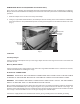
BUMPER BAR INSTALLATION (RANGES ON CASTERS ONLY) There are 2 sets of bumper bars packaged separately and placed inside the oven compartment for shipping. Bumper bars must be installed on the side(s) of the convection oven that is placed near a combustible wall during operation. 1. Remove bumper bars from the oven cavity and unwrap. 2. Using a 5¦16" (8) socket and socket driver, attach bumper bar to the side(s) of the oven nearest the combustible wall.
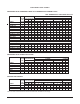
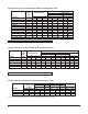
ELECTRICAL DATA CHARTS VR RANGES WITH STANDARD OVENS OR VS RANGES WITH CABINET BODY "N/A" RANGES NOT AVAILABLE 480 VOLT 3 PHASE LOAD TOTAL KW PER PHASE KW 208V 240V 480V MODEL CONN. X-Y Y-Z X-Z VR1,2,5 21.7 7.7 5 9 VR1,2,5 / VB73 27.7 10.7 8 — VS,VM1,2,5 15 5 5 5 VS,VM1,2,5 / VB73 21 8 8 — VR3,6,7 20.7 7.7 5 8 VR3,6,7 / VB73 26.7 10.7 8 — VS,VM3,6,7 14 5 5 4 VS,VM3,6,7 / VB73 20 8 8 — VR4 18.7 6.7 4 8 VR4 / VB73 24.7 9.7 7 8 VS,VM4 12 4 4 4 VS,VM4 / VB73 18 7 7 — 480 Volt Only: VR1,2,5 / VB73 21.7 7.
220/380, 240/415 VOLT VS/VM RANGES AND VR RANGES WITH OVEN MODEL VR1,2,5 VR1,2,5 / VB73 VS,VM1,2,5 VS,VM1,2,5 / VB73 VR3,6,7 VR3,6,7 / VB73 VS,VM3,6,7 VS,VM3,6,7 / VB73 VR4 VR4 / VB73 VS,VM4 VS,VM4 / VB73 TOTAL KW CONN. 21.7 27.7 15 21 20.7 26.7 14 20 18.7 24.7 12 18 3 PHASE LOAD KW PER PHASE X-N 7.7 10.7 5 8 6.7 9.7 4 7 6.7 9.
OPERATION WARNING: THE RANGE AND ITS PARTS ARE HOT. USE CARE WHEN OPERATING, SERVICING AND CLEANING THE RANGE. WARNING (CONVECTION OVEN MODELS ONLY): WHEN USING CONVECTION OVENS, DO NOT STAND DIRECTLY IN FRONT OF OVEN WHILE OPENING DOOR. ALTHOUGH OPENING OVEN DOOR WILL AUTOMATICALLY SHUT OFF THE FAN, SOME HEAT ESCAPES. STEP AWAY TO AVOID HOT AIR.
Oven Controls Thermostat — (located on the right side of the switch panel) controls and maintains oven temperature around the desired set temperature. Temperature range of the oven is from 175°F to 550°F (79-288). VRC Oven ON-OFF Switch (Convection Oven) — a rocker-type switch that works in conjunction with the electric supply of the thermostat and heating elements operating the oven. This switch must be in the ON position for the oven to operate.
High-Speed Units High-speed units furnished on 208 and 240 volt models are controlled by infinite switches. Optional French Hot Plate French hot plates are furnished in lieu of high-speed units. Designed for bulk cooking and stock pot work (up to 20 Qt. stock pots or 9-10" [229-254] dia. pans). Stock pots of over 5-gallon capacity are not recommended for continuous use on French hot plate sections. 208/240 volt units are controlled by infinite heat switches.
To operate the convection oven, arrange oven racks as required, turn the power switch to ON and set the thermostat dial to the desired temperature setting. Allow the oven indicator light to cycle on and off at least twice to ensure that the oven has reached the preset cooking temperature. Load product as quickly as possible. Place pans on center of racks. After cooking is completed, open oven door and unload product.
CLEANING WARNING: DISCONNECT ELECTRICAL POWER SUPPLY BEFORE CLEANING. Daily (Or As Necessary) 1. Empty and clean grease drains and troughs. Do not line trays or trough with heat reflecting foil. 2. While still warm, wipe surface tops with a cloth or other grease absorbing material (or scrape if necessary) to remove spillover, grease, etc., before they burn in. A crust on top of the range will interfere with the cooking capabilities of the range. 3. Keep oven areas clean to prevent smoking.
This page intentionally left blank 16
Cette page a été intentionnellement laissée en blanc 16
NETTOYAGE AVERTISSEMENT : COUPER L’ALIMENTATION ÉLECTRIQUE AVANT DE PROCÉDER AU NETTOYAGE. Nettoyage quotidien (ou au besoin) 1. Nettoyer et vider les plateaux et les godets à graisse à tous les jours. Ne pas recouvrir de papier d’aluminium réfléchissant la chaleur. 2. Pendant qu’elles sont encore chaudes, essuyer (ou racler au besoin) les surfaces à l’aide d’un chiffon qui absorbe la graisse afin d’enlever les débordements, la graisse, etc. avant qu’ils ne brûlent.
Positionner les clayettes selon les besoins, mettre l’interrupteur général à «ON» (MARCHE) et régler le thermostat à la température désirée. Laisser le voyant s’allumer et s’éteindre au moins deux fois pour s’assurer que le four a atteint la température de cuisson désirée. Charger les aliments aussi rapidement que possible. Déposer les bacs au centre des clayettes. Lorsque les aliments sont cuits, ouvrir la porte et les sortir du four.
Éléments à chauffe rapide Les éléments à chauffe rapide utilisés avec les modèles fonctionnant à 208 et 240 V sont commandés par des commutateurs à réglage continu. Plaque circulaire en option Les plaques circulaires en remplacement des éléments chauffants à chauffe rapide conviennent à la cuisson en vrac d’aliments et l’utilisation de marmites (marmites jusqu’à 20 pte ou casseroles de 229 à 254 mm [9 à 10 po] de diamètre). On ne recommande pas l’utilisation continue de marmites de plus de 5 gal.
Commandes du four Thermostat – (Situé du côté droit du tableau de commande) Commande et maintient le four à la température désirée. La gamme de température du four varie de 79 à 288 °C (175 à 550 °C). Interrupteur «ON-OFF» (MARCHE-ARRÊT) du four VRC (four à air pulsé) – Interrupteur à berceau fonctionnant conjointement avec l’alimentation électrique du thermostat et des éléments chauffants du four. Doit être à «ON» (MARCHE) pour que le four fonctionne.
FONCTIONNEMENT AVERTISSEMENT : LA CUISINIÈRE ET SES COMPOSANTS SONT CHAUDS. EXERCER UNE EXTRÊME PRUDENCE LORS DE SON UTILISATION, ENTRETIEN ET NETTOYAGE. AVERTISSEMENT (FOUR À AIR PULSÉ SEULEMENT) : NE PAS SE TENIR DEVANT LE FOUR À L’OUVERTURE DE LA PORTE. MÊME SI LE VENTILATEUR SE MET AUTOMATIQUEMENT EN MARCHE À L’OUVERTURE DE CELLE-CI, UNE CERTAINE QUANTITÉ D’AIR CHAUD S’ÉCHAPPE. SE TENIR ÉLOIGNÉ DE LA PORTE.
CUISINIÈRES VS, VM ET VR À FOUR 220-380 ET 240-415 V MODÈLE VR1,2,5 VR1,2,5 / VB73 VS,VM1,2,5 VS,VM1,2,5 / VB73 VR3,6,7 VR3,6,7 / VB73 VS,VM3,6,7 VS,VM3,6,7 / VB73 VR4 VR4 / VB73 VS,VM4 VS,VM4 / VB73 PUIS. TOT.
TABLEAU DES CARACTÉRISTIQUES ÉLECTRIQUES CUISINIÈRES VR À FOUR CONVENTIONNEL ET CUISINIÈRES VS AUTOPORTANTES N/O = CUISINIÈRES 480 V NON OFFERTES MODÈLE VR1,2,5 VR1,2,5 / VB73 VS,VM1,2,5 VS,VM1,2,5 / VB73 VR3,6,7 VR3,6,7 / VB73 VS,VM3,6,7 VS,VM3,6,7 / VB73 VR4 VR4 / VB73 VS,VM4 VS,VM4 / VB73 480 V seulement : VR1,2,5 / VB73 VR3,6,7 / VB73 VS,VM1,2,5 / VB73 VS,VM3,6,7 / VB73 VR4 / VB73 VS,VM4 / VB73 PUIS. TOT.
INSTALLATION DES BARRES DE CHOC (CUISINIÈRES SUR ROULETTES SEULEMENT) Deux paires de barres de choc emballées séparément sont expédiées dans l’enceinte du four. Poser ces barres du ou des côtés du four à air pulsé qui se trouvent à proximité d’un mur combustible. 1. Sortir les barres de choc du four et les déballer. 2. Au moyen d’une clé et d’une douille de 8 mm (5/16 po), fixer la barre de choc du ou des côtés les plus près du mur combustible.
MODÈLE DESCRIPTION CUISINIÈRES AUTOPORTANTES VS1 VS2 VS3 VS4 VS5 VS6 VS7 Trois plaques à bouillir de 305 x 610 mm (12 x 24 po). Trois plaques tout usage de 305 x 610 mm (12 x 24 po); les plaques de droite et de gauche sont pourvues d’une rainure de récupération de la graisse, mais non celle du centre. Deux plaques circulaires de 241 mm (9 1/2 po) de diam. à gauche et deux plaques à bouillir de 305 x 610 mm (12 x 24 po), une au centre et l’autre à droite.
GÉNÉRALITÉS Les cuisinières électriques Vulcan à four conventionnel des séries VR, VS, VM, VEX et VMX et à four à air pulsé de la série VRC offrent les caractéristiques suivantes : MODÈLE DESCRIPTION CUISINIÈRES À FOUR CONVENTIONNEL VR1 VR2 VR3 VR4 VR5 VR6 VR7 Trois plaques à bouillir de 305 x 610 mm (12 x 24 po). Trois plaques tout usage de 305 x 610 mm (12 x 24 po); les plaques de droite et de gauche sont pourvues d’une rainure de récupération de la graisse, mais non celle du centre.
VM1 VM2 CONFIGURATIONS DES CUISINIÈRES VULCAN VULCAN RANGE CONFIGURATIONS VMX1 VMX2 VEX1 VEX2 VMX3 VEX3 5
VR1, VR2 VM1, VM2 VS1, VS2 VR1C, VR2C CONFIGURATIONS DES CUISINIÈRES VULCAN VR3, VR6 VM3, VM6 VS3, VS6 VR3C, VR6C VR5 VM5 VS5 VR5C VR4 VR3, VR6 VR7 VM4 VM3, VM6 VM7 VS4 VS3, VS6 VS7 VR4C VR3C, VR6C VR7C (SHOWN WITH OPTIONAL (ÉLÉMENTS À HIGH SPEED ELEMENTS) CHAUFFE RAPIDE EN OPTION) SÉRIE VR VR SERIES SÉRIE VRC VRC SERIES SÉRIE VS VS SERIES PL - 51130-1 4
Installation et fonctionnement CUISINIÈRES ÉLECTRIQUES À SERVICE INTENSE MODÈLES VR, VS, VM, VEX, VMX ET VRC DOCUMENT À CONSERVER EN CAS DE BESOIN. Les appareils Vulcan sont fabriqués avec le plus grand soin et à partir des meilleurs matériaux. Leur installation, utilisation et entretien appropriés permettront d’en obtenir un rendement optimal pendant de nombreuses années. On recommande de lire ce manuel au complet et de suivre attentivement toutes les instructions.
Leur fabrication ayant cessé, les modèles suivants ne sont plus offerts : VR1(C) VR3(C) VR6(C) VR7(C) VS1 VS3 VS6 VS7 VM1 à VM7 VMX1 VMX2 VMX3 VEX1 2
MODE D'EMPLOI CUISINIÈRE ÉLECTRIQUE À SERVICE INTENSE MODÈLES VR, VS, VM, VEX, VMX ET VRC Cuisinière électrique VR4 VULCAN-HART DIVISION OF ITW FOOD EQUIPMENT GROUP, LLC P.O. BOX 696, LOUISVILLE, KY 40201-0696 TÉL. (502) 778-2791 F33210 (Rév. A 1-04) www.vulcanhart.